
220 MHz Twin-Lead J-Pole
A homebrew antenna for the 1.25 m (220 MHz) band, built from Ed Fong WB6IQN's design: 300-ohm twin lead inside a capped ¾-inch PVC pipe.
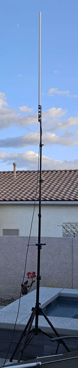
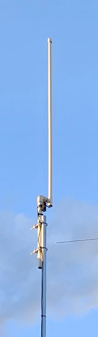
The 1.25 m band (222–225 MHz) is a quiet, useful ham band, but there aren't many antennas made for it. Ed Fong's twin-lead J-pole is a simple answer: a length of 300-ohm TV twin lead, cut and notched to size, with the coax soldered on at the bottom. It needs no radials, and the whole antenna slides inside a ¾-inch PVC pipe that is capped at the top, which keeps it out of the weather.
The design is Figure 3 in Ed's tri-band antenna article (QST, March 2017). I built mine in April 2025, tested it on a tripod in the backyard, and it now stands about 22 feet above the ground as antenna #1 in my antenna farm.
Dimensions
From Ed Fong's Figure 3, top to bottom, for a pipe of ¾-inch 200 psi PVC.
| Section | Length | Notes |
|---|---|---|
| Radiator | 26″ | Both conductors, above the notch |
| Notch | ¼″ | Cut out of one conductor only |
| Matching section | 9″ | Below the notch |
| Bottom | ¾″ | The coax is spliced on here, and the two conductors are shorted together |
Ed's figure uses thin RG-174A coax for the lead inside the pipe.
The build
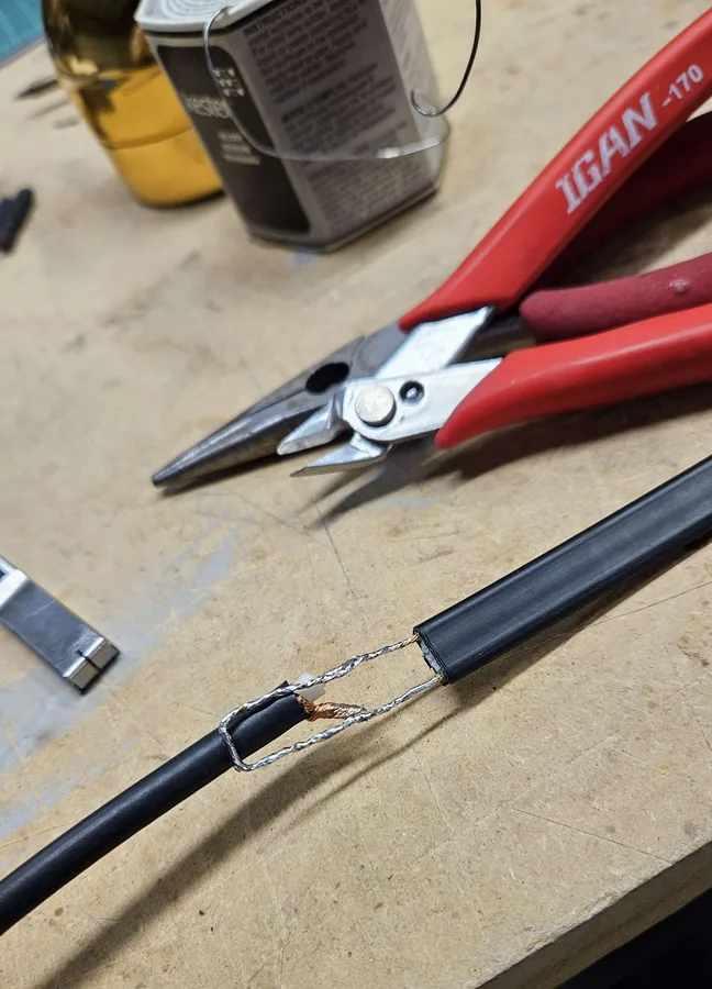
- Cut the twin lead to 36 inches and cut the ¼-inch notch in one conductor, 26 inches from the top.
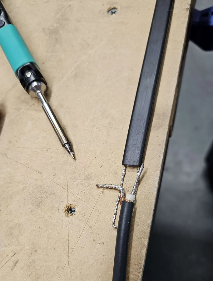
- Attach the coax at the bottom: solder the center conductor and shield to the twin lead and short the two conductors together, as in the figure.
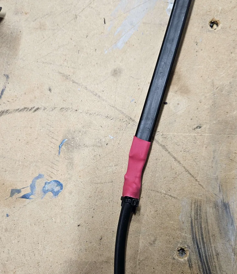
- Seal the splice with heat shrink.
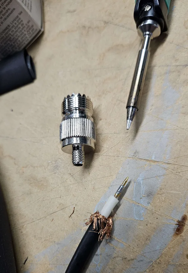
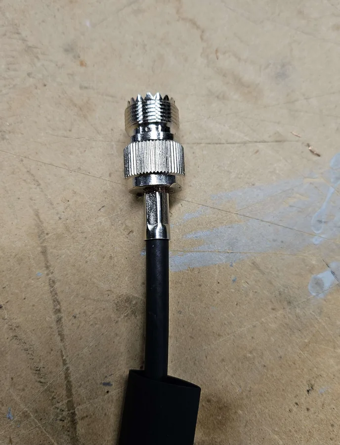
- Fit the connector on the other end of the coax.
- Slide it into the PVC pipe and cap the top.
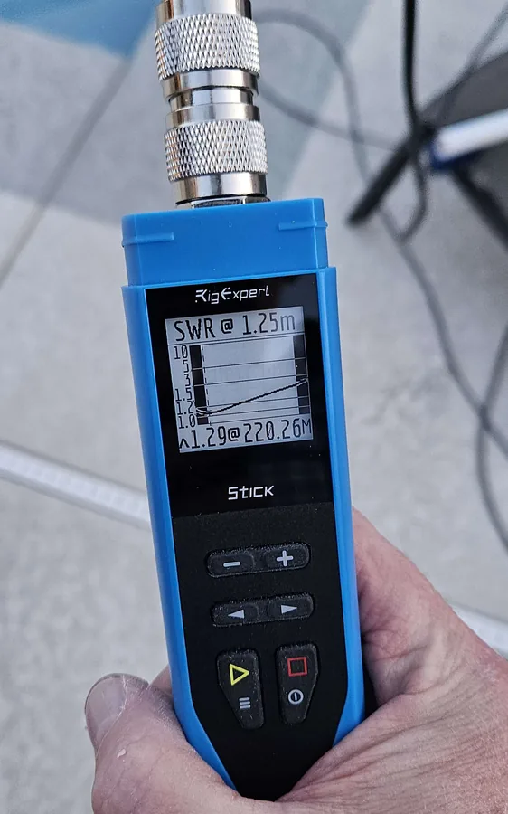
- Test before installing: on a tripod in the backyard the SWR was 1.29:1 at 220.26 MHz.
Parts
- 300-ohm twin lead, 36 inches
- Coax for the lead inside the pipe (Ed's figure uses RG-174A), and a UHF connector
- Heat shrink for the splice
- ¾-inch 200 psi PVC pipe and a cap
Links
Credits
The antenna design and dimensions are by Edison Fong, WB6IQN, from his article "A Tri Band Antenna for 2 meters, 220 MHz, and 70cm Antenna Without Radials" (QST, March 2017).