
50 µA Constant Current Source
A small test source that puts out a steady 50 microamps, built to check the microamp range of a newly acquired multimeter.
I recently acquired a used B&K Precision 5470 multimeter. I wanted to check that its microamp range could be trusted, and a constant current source is a good way to do that: it gives a known current regardless of what it's connected to. So I built a 50 µA constant current source on a breadboard, from a design by Alan Wolke, W2AEW, who shows it in his video #324, “How to ‘calibrate’ the Simpson 260 VOM – BONUS: 50 microamp current source”. The current source part starts at about 14 minutes in.
I compared its output on the B&K against my calibrated Simpson 270 analog meter. At 50 µA the B&K was spot on.
The build
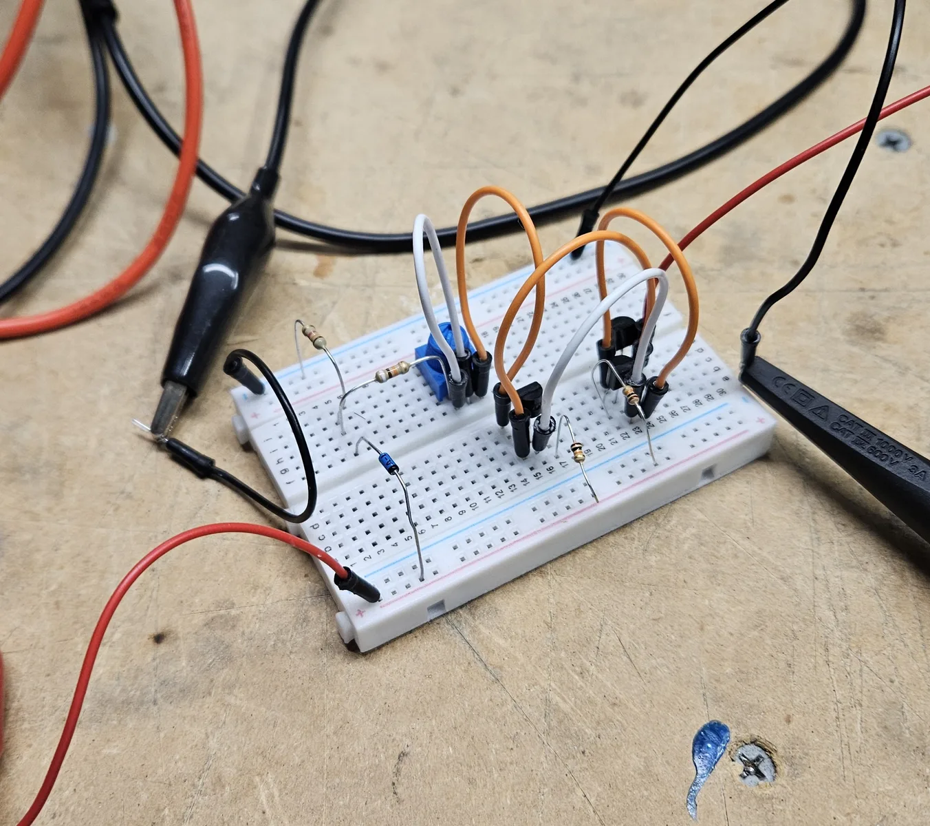
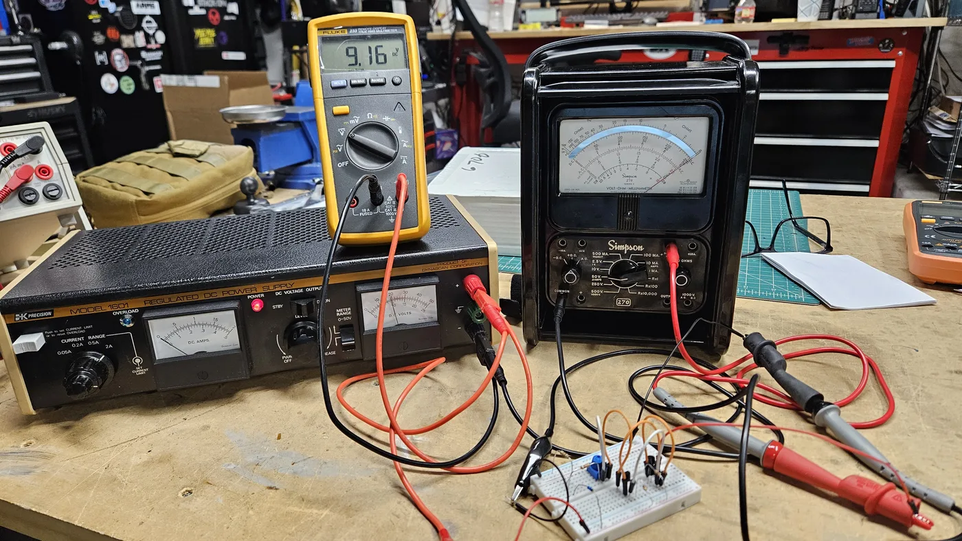
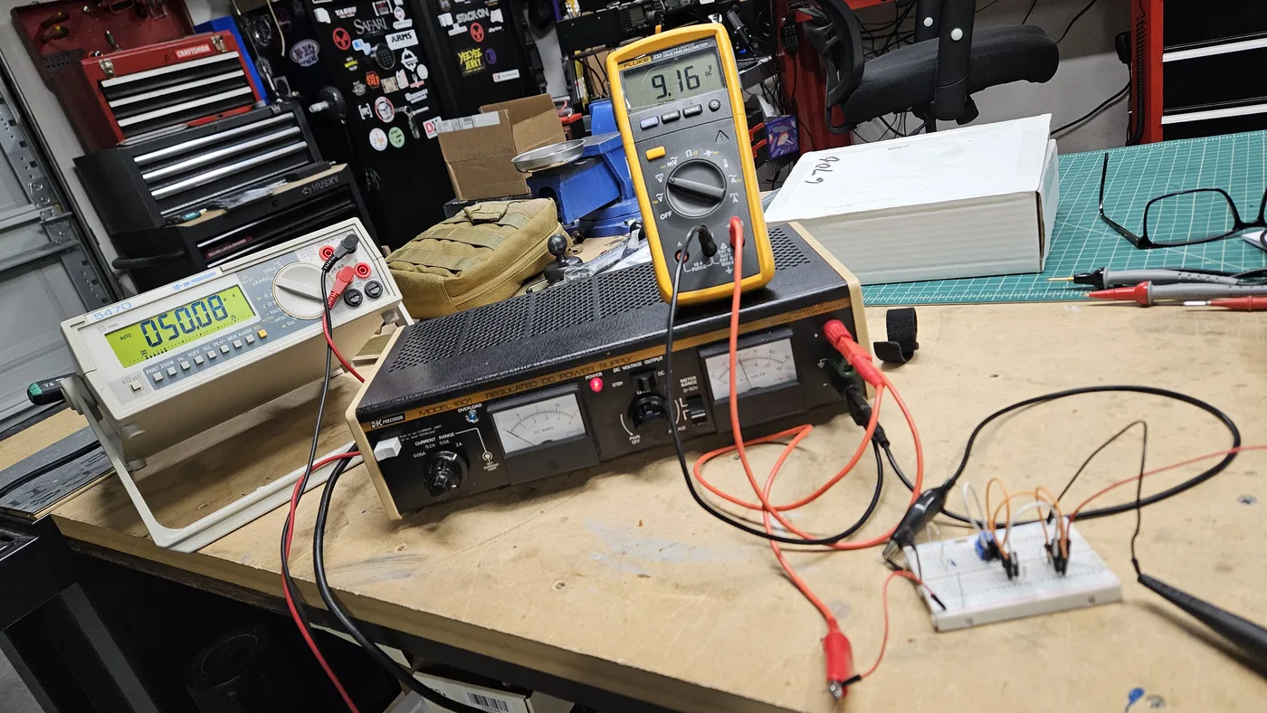
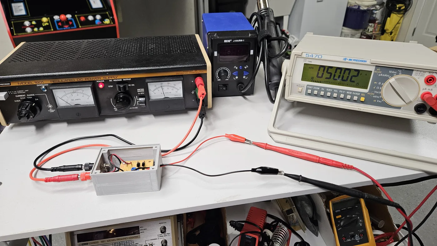
- Breadboard. I built the circuit on a breadboard first and powered it from my B&K 1601 power supply, using a Fluke meter to confirm that the input was 9 volts.
- Checking the current. With the output measured on the B&K 5470 and on the Simpson 270, both showed 50 µA. A small trimmer sets the exact current.
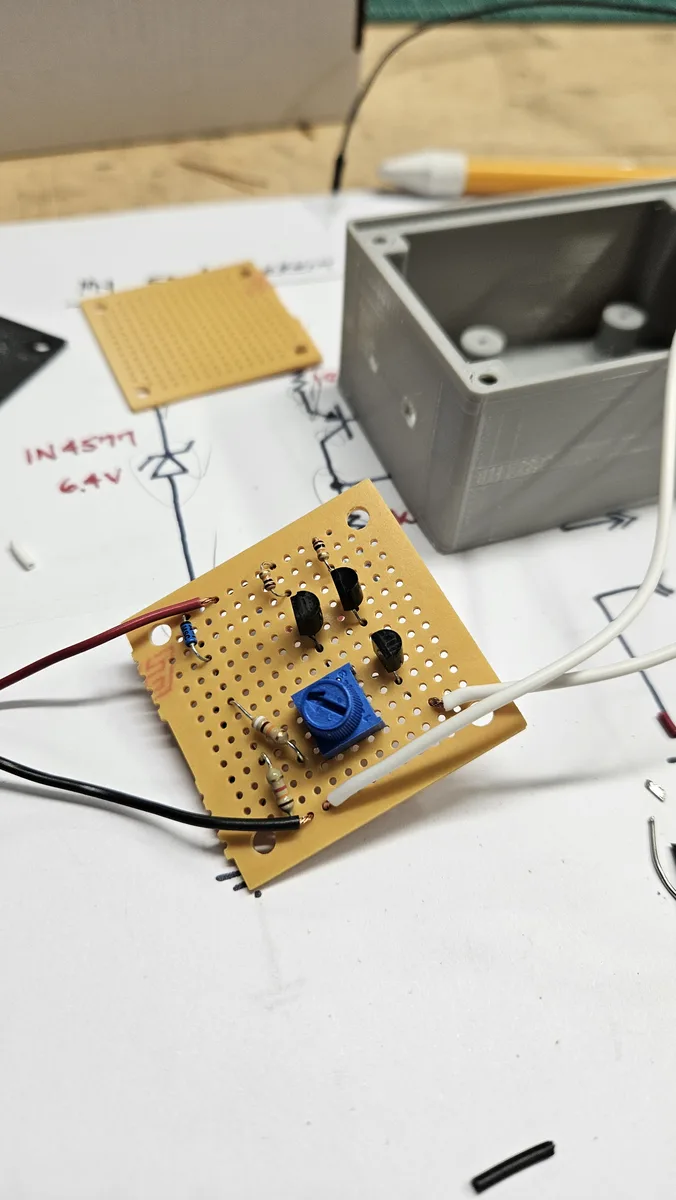
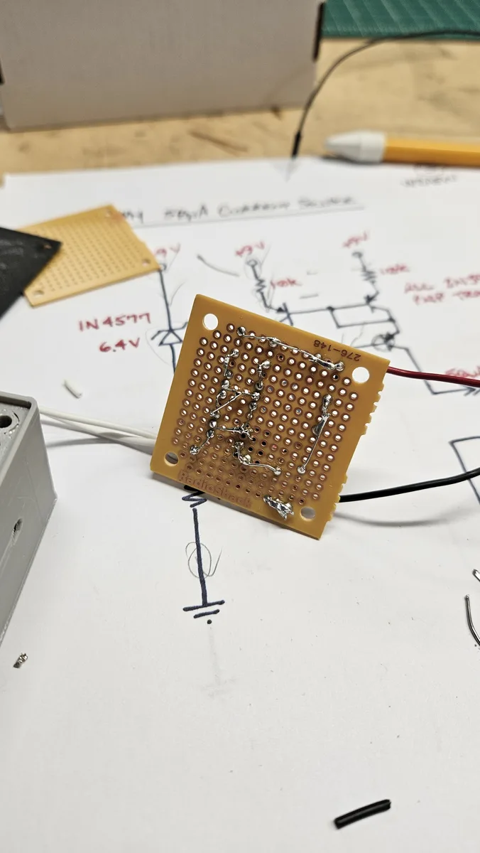
- Perfboard. Once it worked, I rebuilt it on a small piece of perfboard.
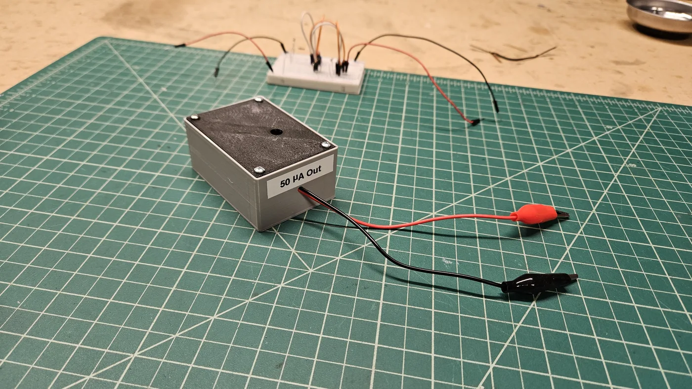
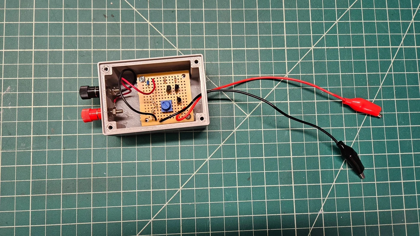
- The case. I printed a box in PETG and put the perfboard inside, with terminals for the 9 volt supply and a pair of leads with alligator clips for the 50 µA output.
- Using it. Apply 9 volts DC to the terminals, and the alligator clips give a 50 µA test current, ready to check any meter.
Parts
- Transistors, a reference diode, resistors and a small trimmer, as in W2AEW’s design (see his video for the schematic and values)
- A small piece of perfboard
- A 3D-printed PETG case, from the Parametric Project Box on Thingiverse
- Terminals for the 9 V input, and leads with alligator clips for the output
- A printed label on the case
Links
Credits
The circuit is a design by Alan Wolke, W2AEW. The case is the Parametric Project Box by Anonaab on Thingiverse, shared under a Creative Commons Attribution license.