
Bird 43 Peak Reading Kit
A kit that lets a Bird 43 wattmeter read peak power as well as average, and stretches the range of each element.
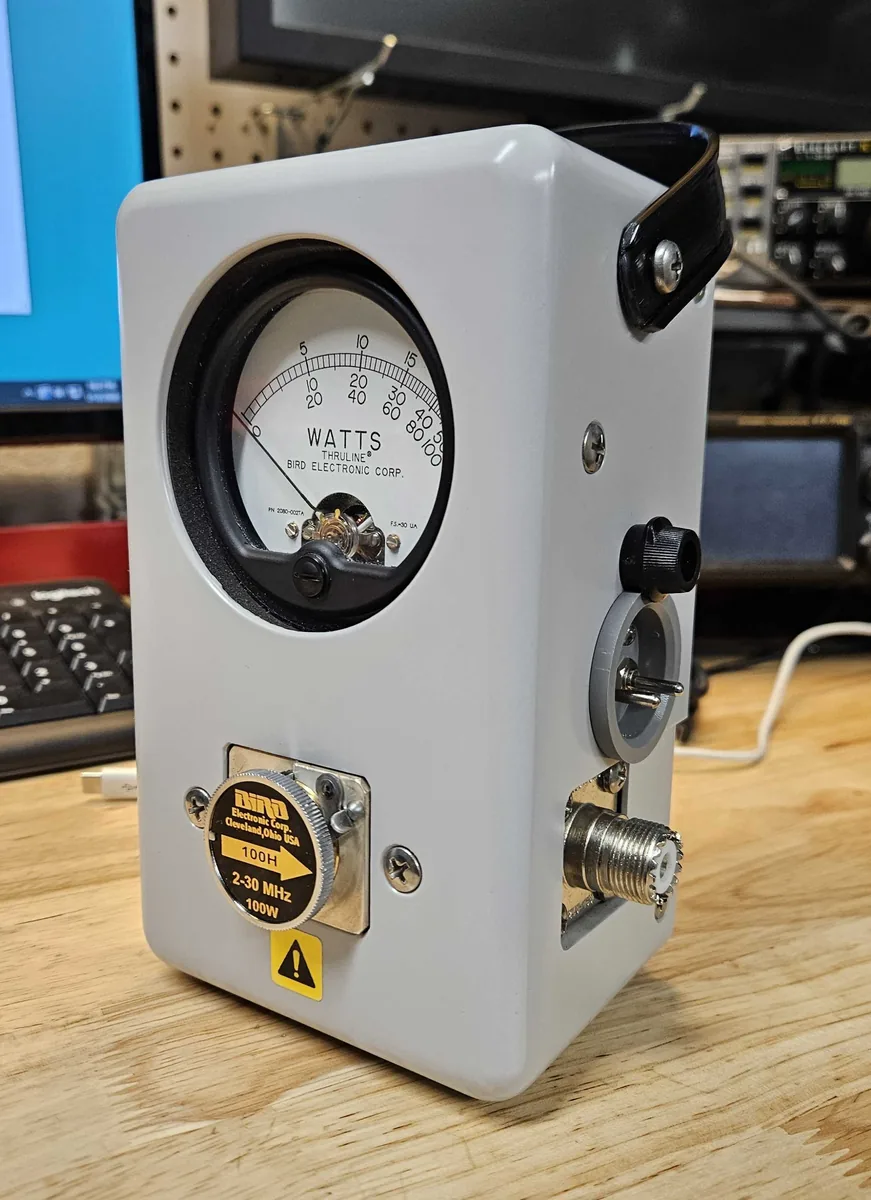
In the winter of 2026 I installed a peak reading kit in my Bird 43 wattmeter. With the flip of a switch, the meter now reads either average (CW) power or peak (PEP) power.
That matters on single sideband. A stock Bird 43 shows average power, and a voice signal jumps around too quickly for the needle to follow, so the reading comes out well below what the radio is really putting out on voice peaks. In the Peak position the kit holds the needle at the top of each peak long enough to read it.
A second switch is a range extender with three positions: Normal, 2x and 5x. With a 100 watt element, for example, it lets the same scale read up to 200 or 500 watts.
1. The kit
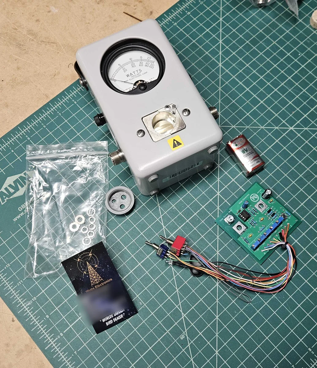
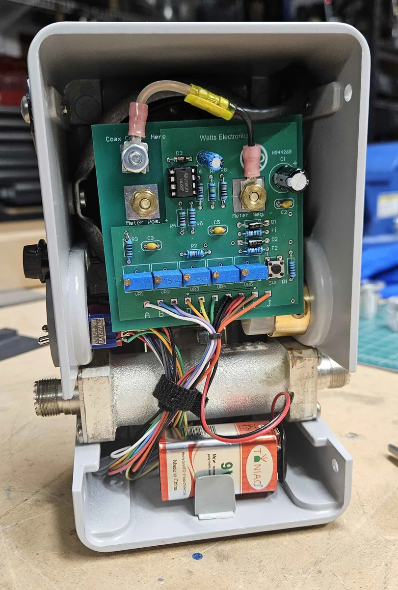
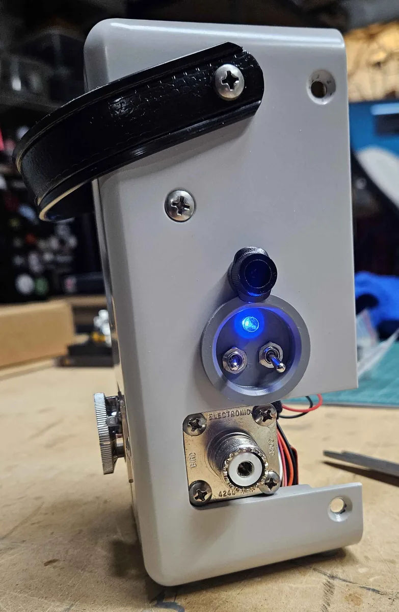
The kit came from Watts Electronics, bought on eBay. It is one circuit board with the two toggle switches and a blue LED already wired to it, a clip for a 9 volt battery, a gray cup that holds the switches, and a small bag of washers.
2. Fitting the board
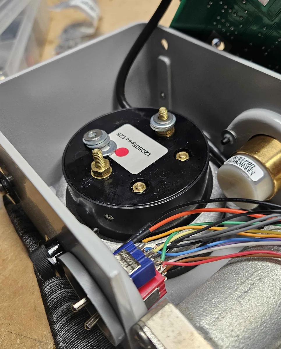
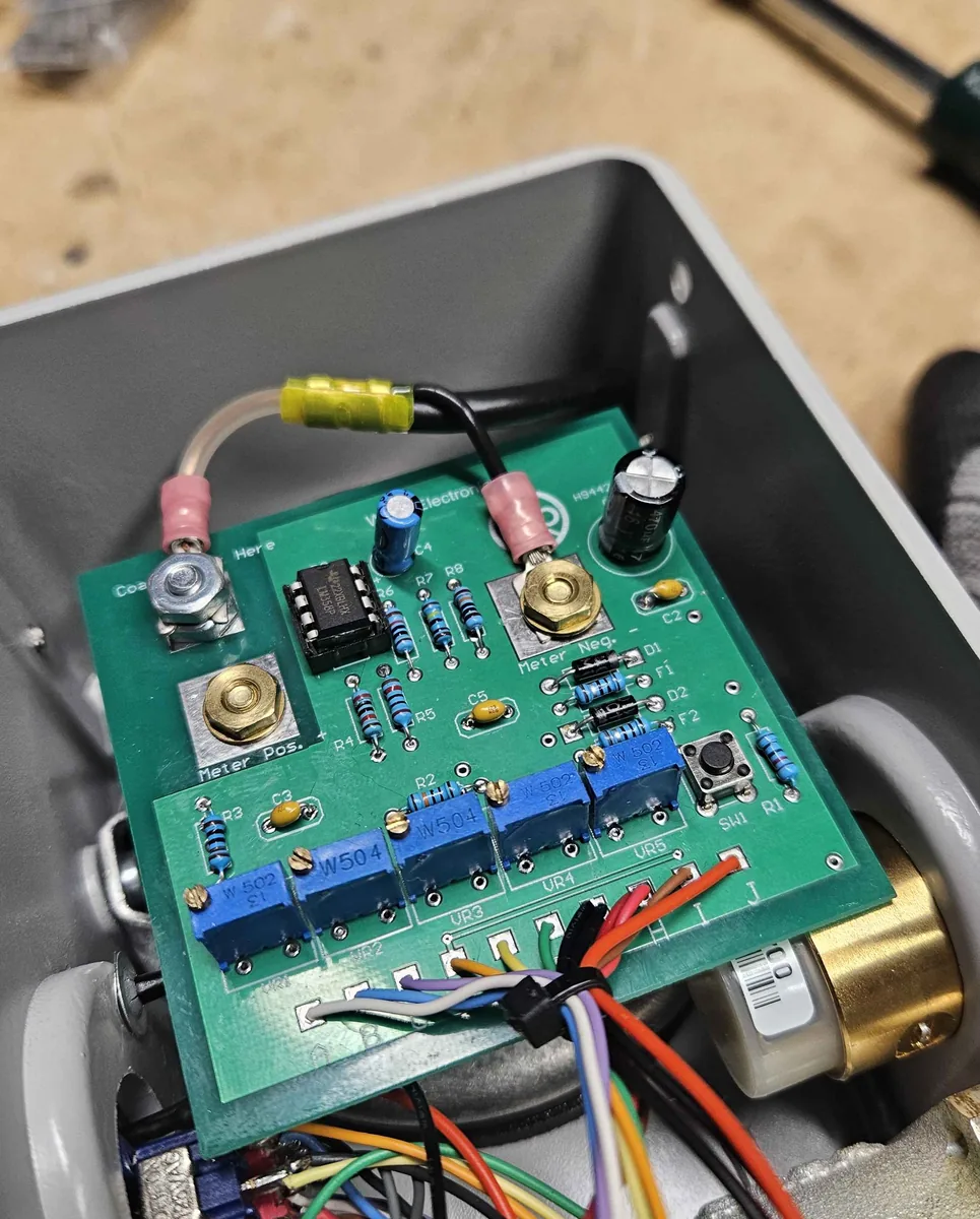
The board mounts on the two terminal studs on the back of the meter, on the pads marked Meter Pos. and Meter Neg., so it needs no other bracket. The lead from the element socket, which used to go to the meter, now goes to the terminal marked “Coax Center Here”. The signal passes through the kit on its way to the meter.
3. Battery and switches
The 9 volt battery sits in the bottom of the case, below the line section. The switches go in the gray cup, which fits a hole that was already in the side of the Bird's case, so there was no drilling or cutting. The blue LED lights up the cup.
4. Calibration
The five trimmers on the board calibrate the needle. The idea is that a steady carrier has the same average and peak power, so the Peak position should show exactly what the Average position shows.
- Zero. With no RF power applied, check that the needle rests exactly on zero. If it doesn't, adjust the zero screw on the face of the meter.
- Average reading. With the switch on Average, apply a steady CW carrier and note the reading.
- Peak. Switch to Peak, press the calibration button on the board, and adjust the trimmer until the needle matches the Average reading.
- Range extender. Check the 2x and 5x positions against known power levels.
Parts
- Bird 43 Thruline wattmeter
- Peak reading and range extender kit from Watts Electronics
- 9 volt battery
- Element shown: Bird 100H, 100 watts, 2–30 MHz