
B&K Precision 1601 Power Supply Repair
A dead 0–50 volt bench supply that kept popping its fuse, and the troubleshooting that brought it back to life.
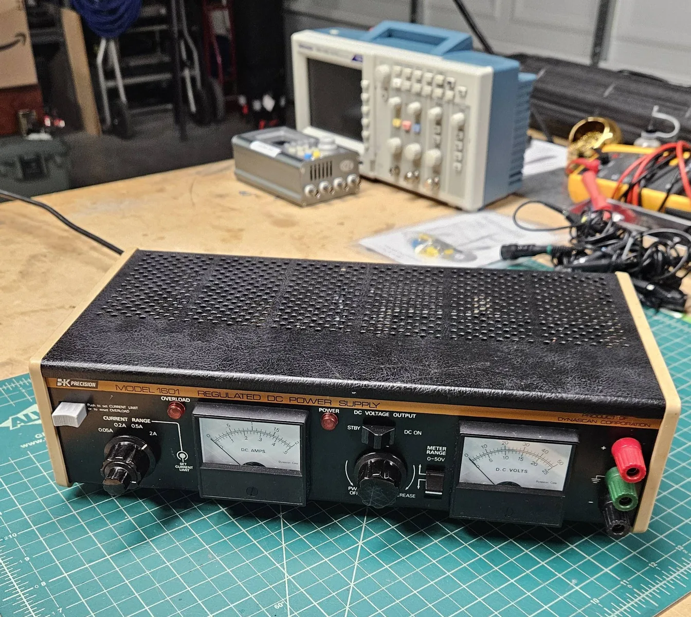
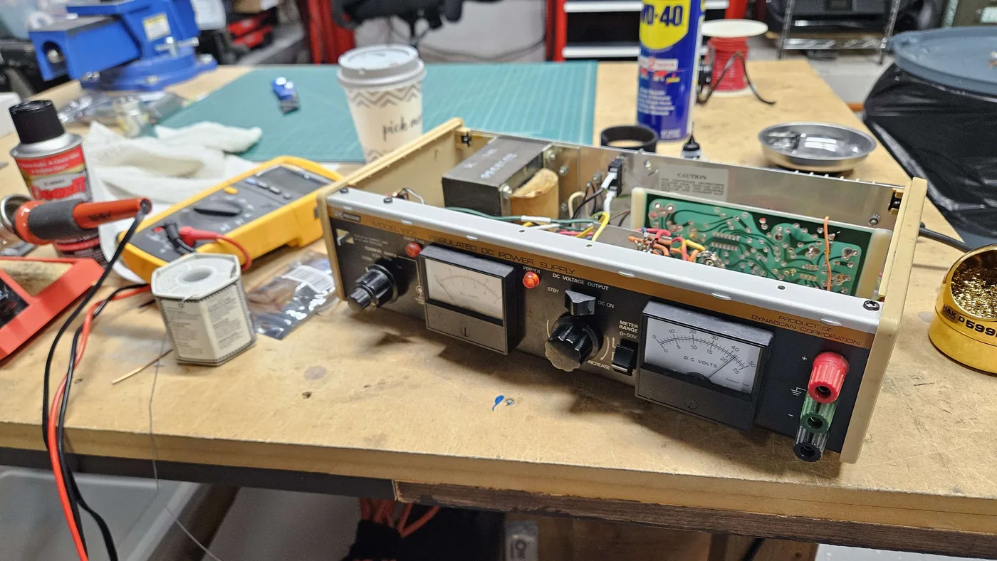
Another operator gave me a B&K Precision Model 1601, a 0–50 volt DC current-limiting variable power supply that wasn't working. It kept popping the glass fuse. I ran out of glass fuses while troubleshooting, so I replaced the fuse with a manually resettable circuit breaker. This is how the rest of the repair went.
1. The fuse keeps blowing
2. The transistor checks out; the rectifier doesn't
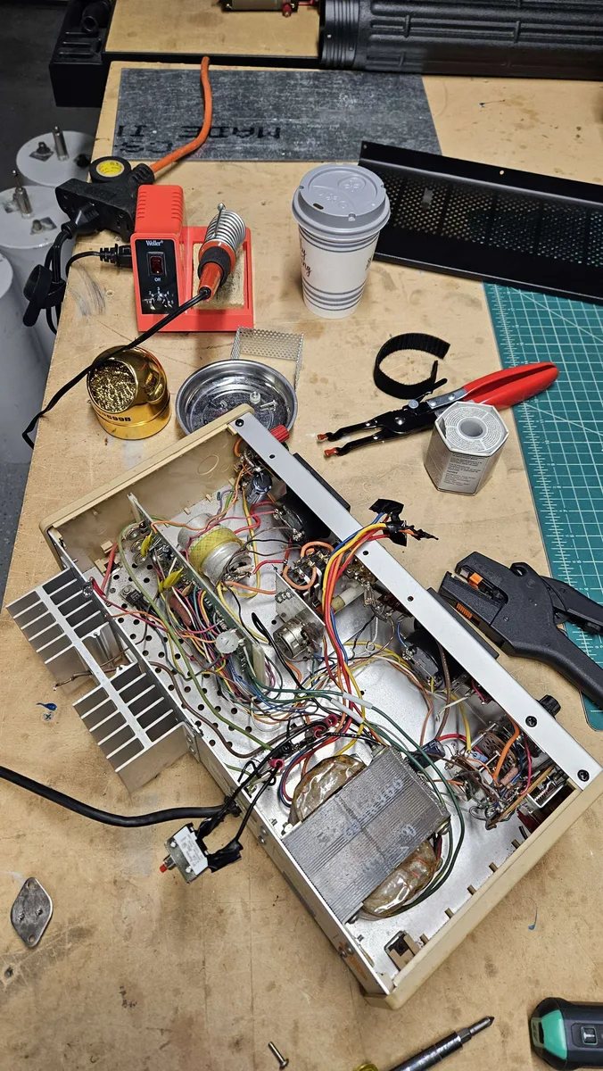
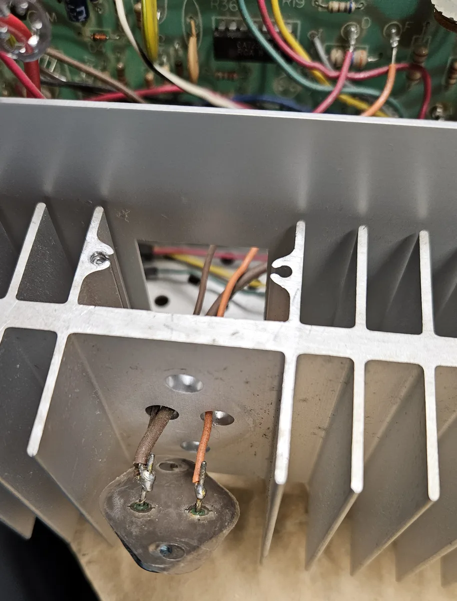
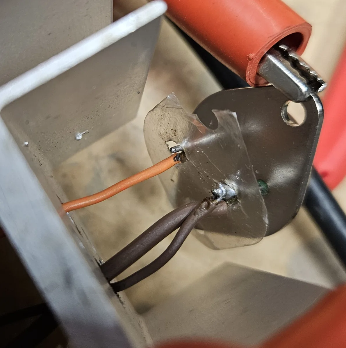
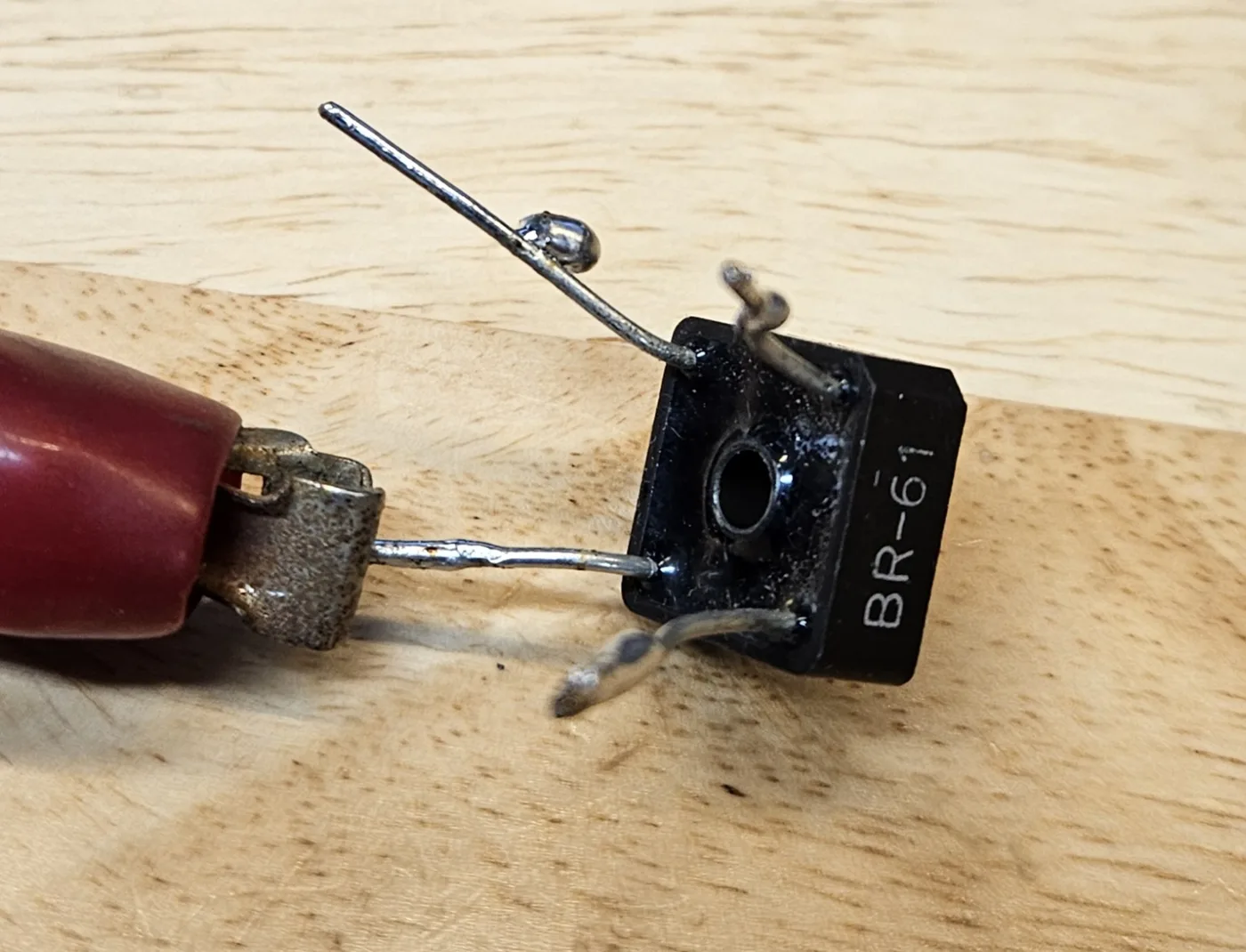
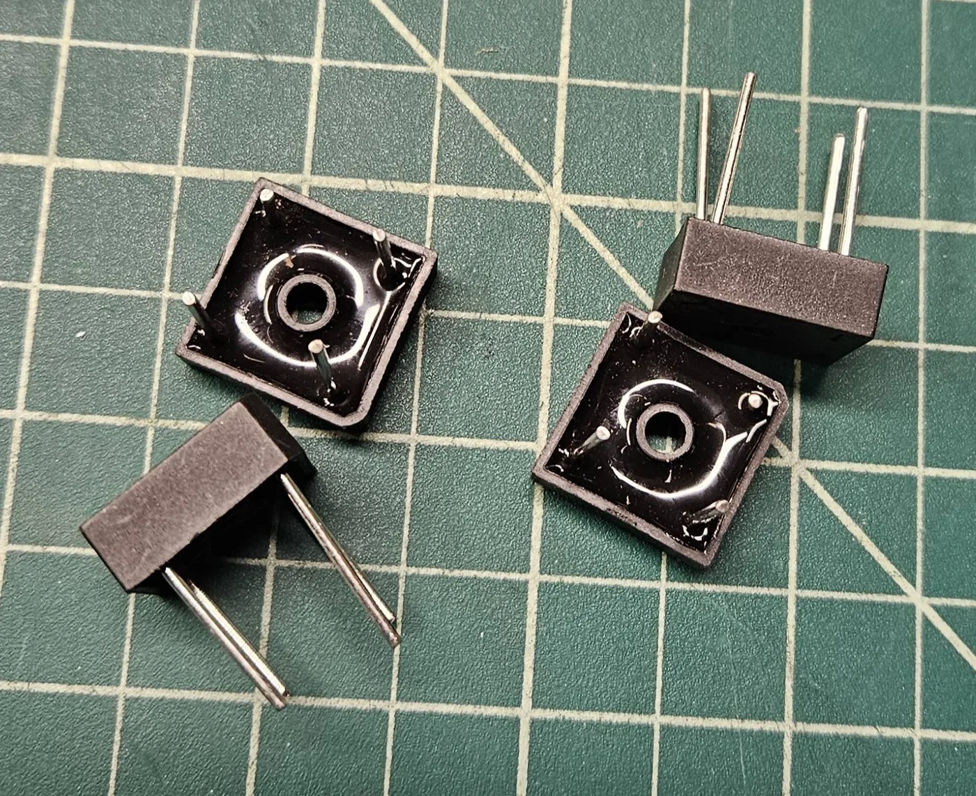
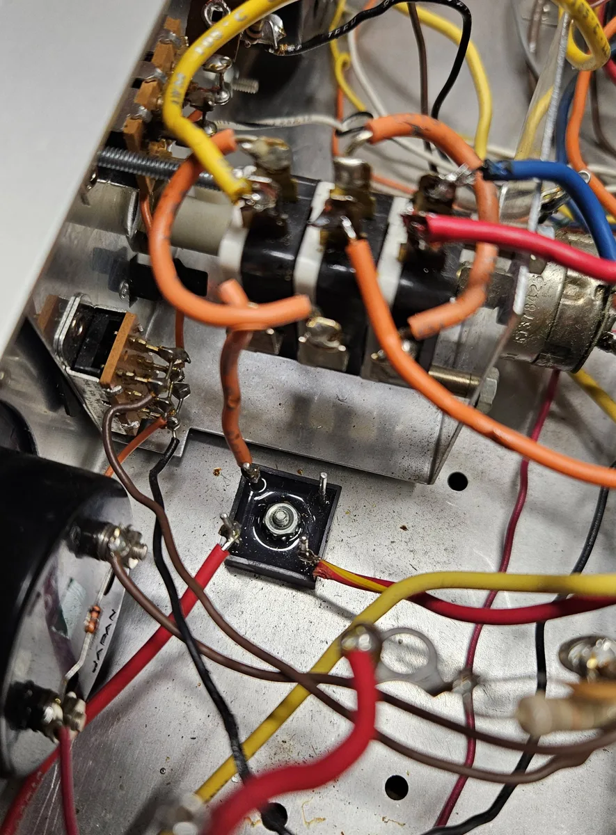
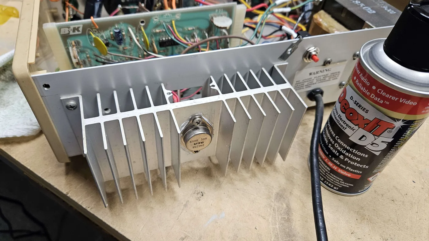
Following a video on YouTube, I tested the power transistor and it checked out OK. I moved on to the bridge rectifier, removed it and followed another video to test it. It tested bad: the diodes in the rectifier were no good. I ordered a replacement rectifier, and a new transistor insulator, because the original one was damaged when I removed the transistor to test it.
3. The filter capacitor
With the new rectifier installed, I found that the filter capacitor was no good. To confirm it, I removed the capacitor completely, and the power supply came to life and gave variable voltage. I was fully confident (famous last words) that this was the last piece of the puzzle. I started putting back what I could: the rectifier, the resettable circuit interrupt in a newly drilled hole, and a lot of the wiring I had disconnected for troubleshooting. I also replaced other caps as needed.
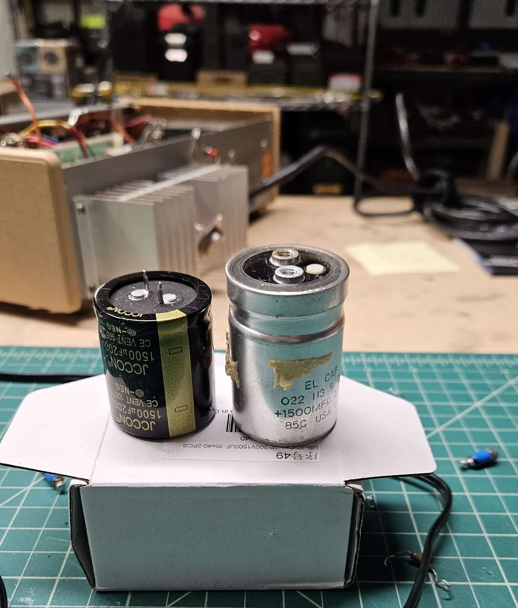
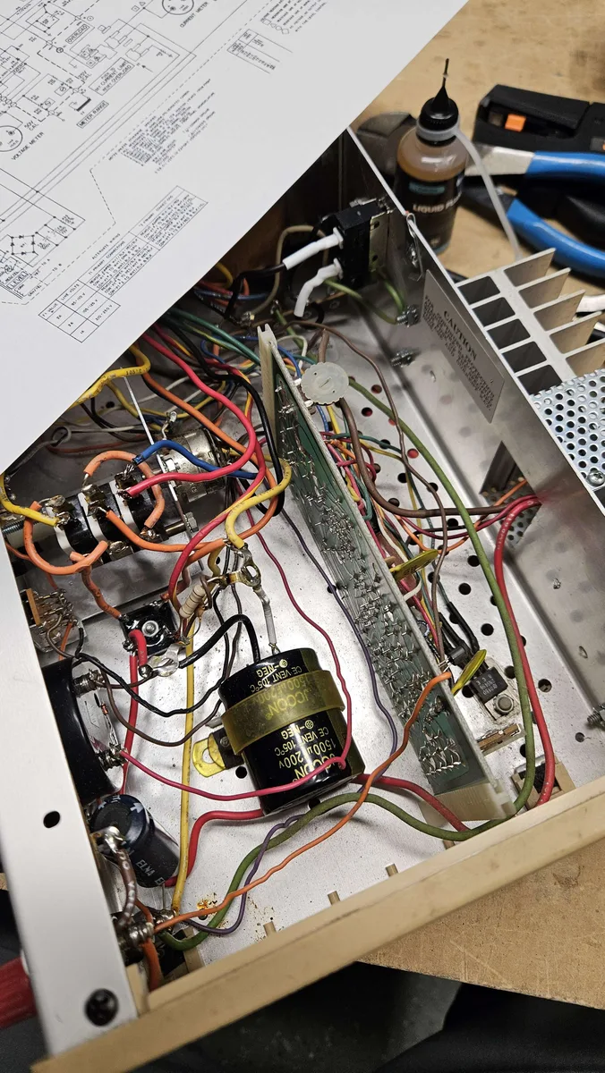
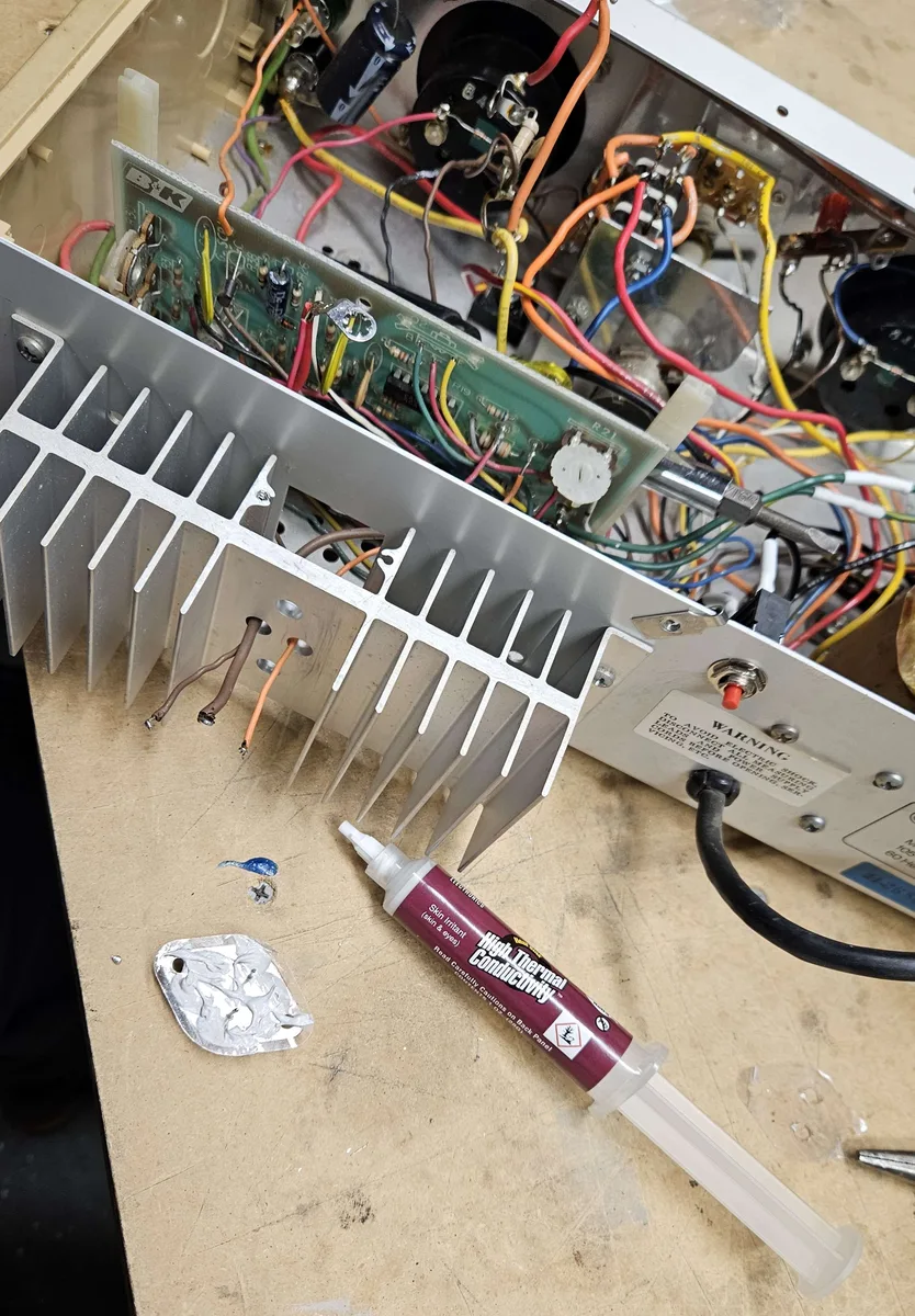
The new capacitor arrived and went in. The old one had screw terminals and the new one has solder leads, so it doesn't look pretty. I installed the transistor with a new mica insulator and fresh conductive paste, and powered it up again. No smoke and nothing blew, which was a good sign.
4. Testing the other capacitors
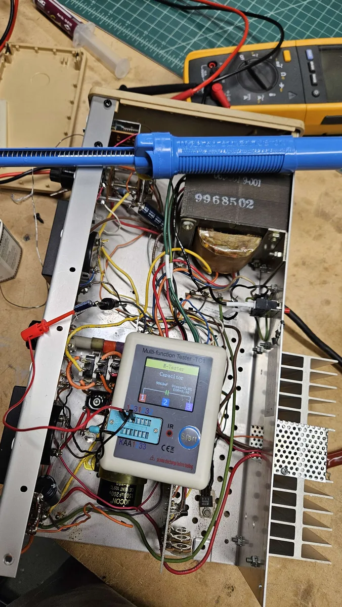
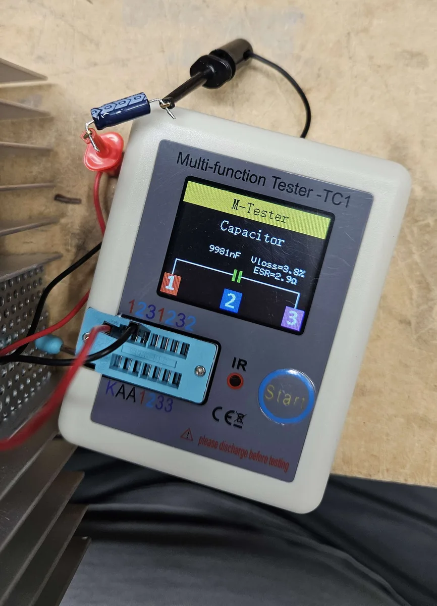
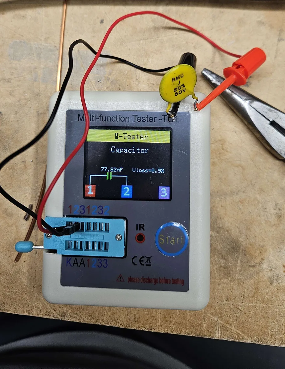
I tested all the other capacitors. One 4.7 µF cap was questionable: its ESR was slightly high, which indicates it's breaking down, so that one was replaced. All the others seemed good.
I learned a few things along the way. You can only test electrolytic capacitors for ESR, because they are the type that breaks down (it's worth searching for ESR, there is lots of information on it). With a $25 tester you can only really check ceramic and film capacitors for capacitance. Thanks to KF7PSM for suggesting the LCR-TC1 tester.
5. A new reset button
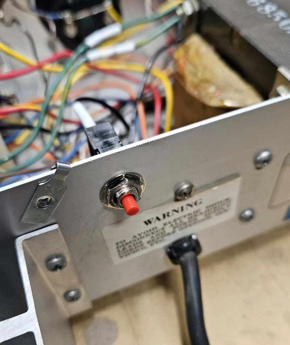
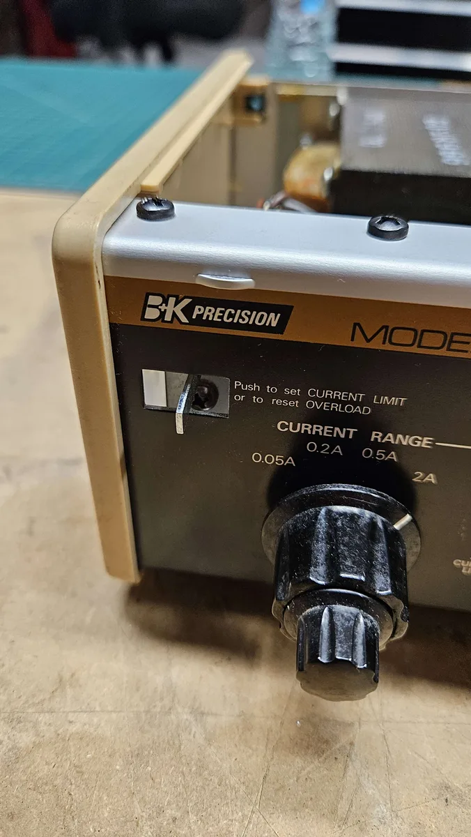
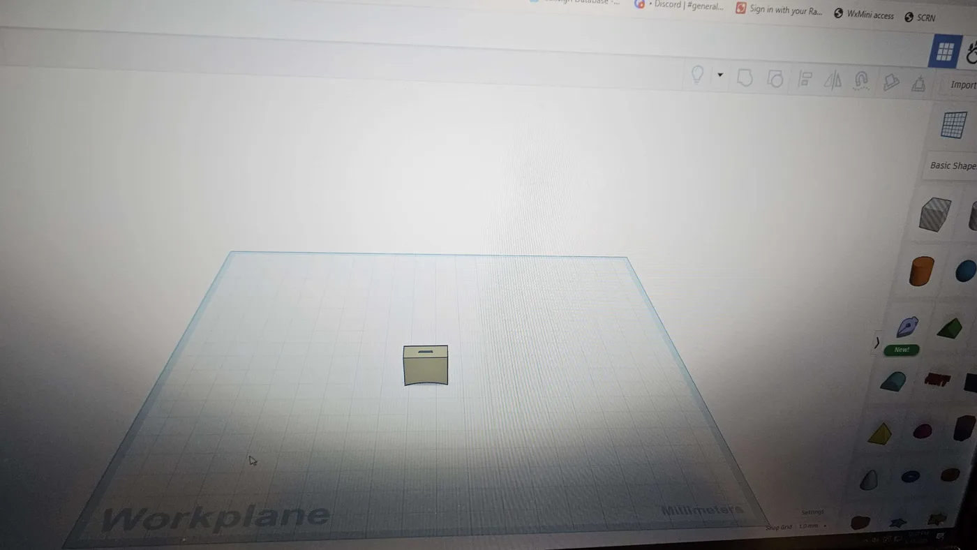
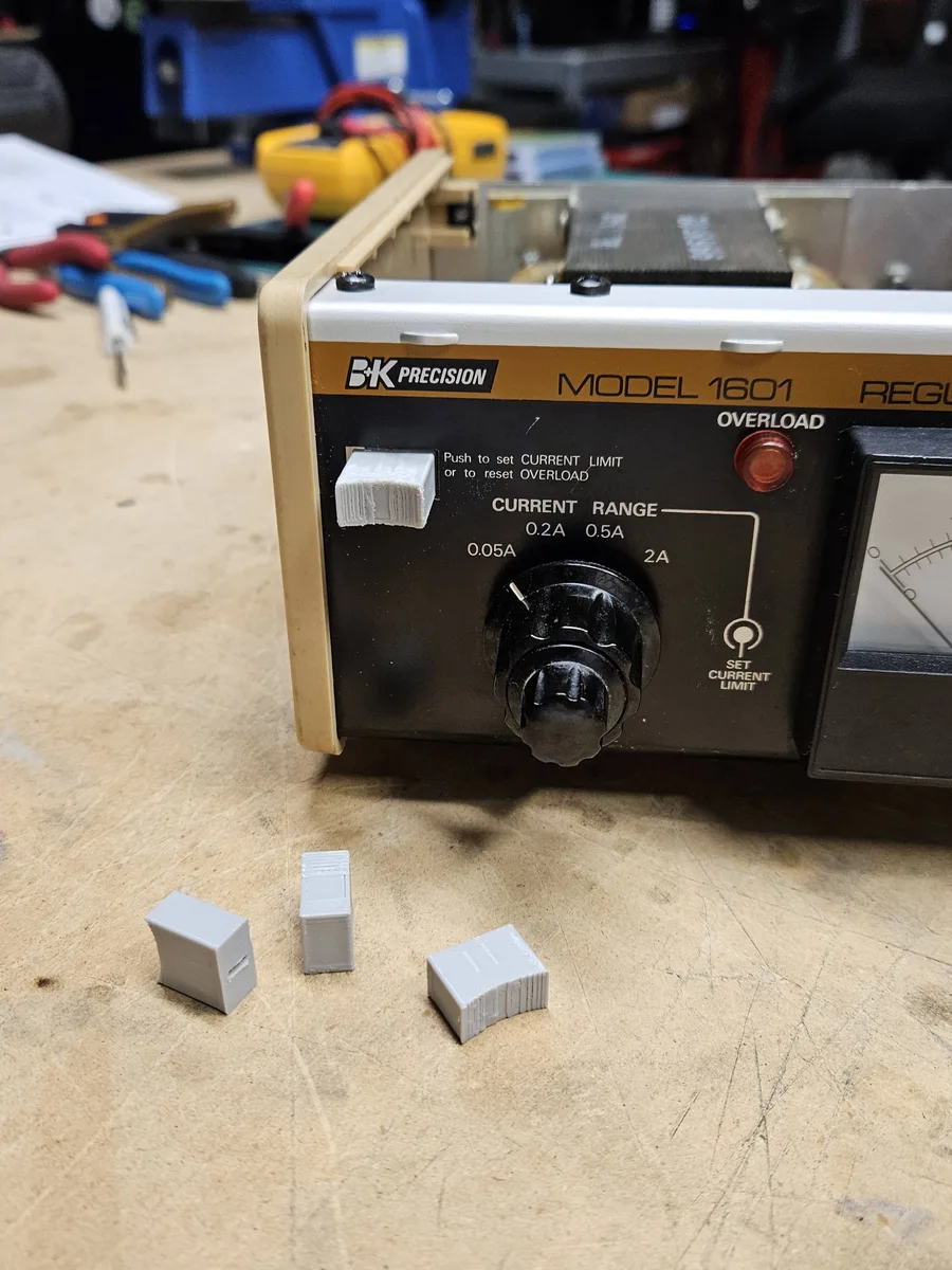
The supply's front panel has a button to set the current limit or to reset an overload, and I designed and printed a new one. I designed it in Tinkercad and printed it in PETG on my Flashforge. It took a few iterations to get it right.
6. Surge protection
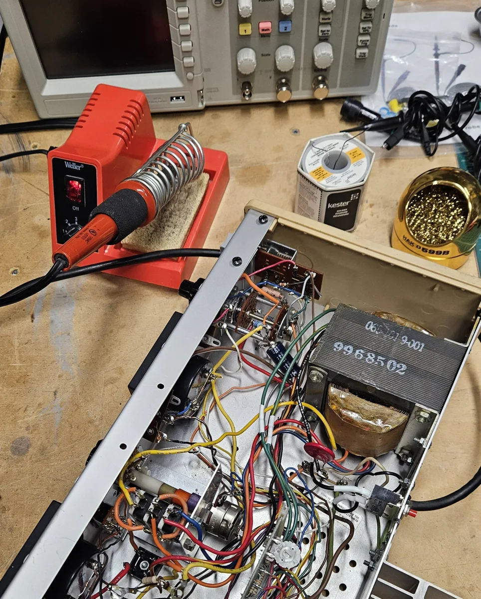
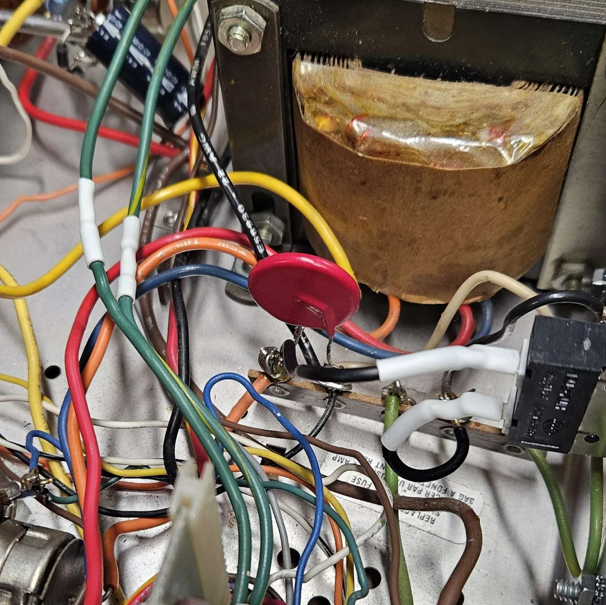
Another operator suggested adding a varistor across the 120 volt AC input to the transformer, for protection against spikes. It's the red disc in the photo.
7. On the oscilloscope
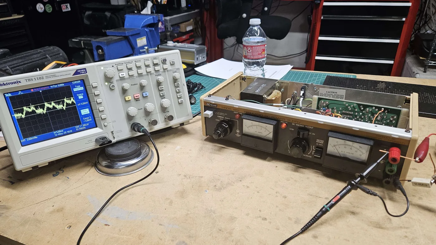
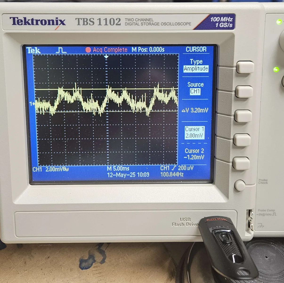
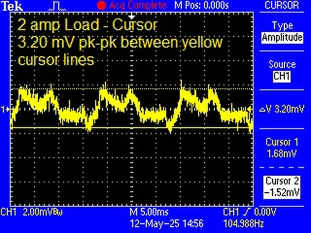
I put the power supply on the oscilloscope. Using a 1 ohm resistor to make a 2 amp load, I checked for ripple and noise. The output voltage was very clean: about 3.2 mV of ripple on 2 volts, or about 0.16 %.
Parts
- Manually resettable circuit breaker (in place of the glass fuse)
- Replacement bridge rectifier (a four-pack)
- New mica transistor insulator and conductive paste
- New filter capacitor, a replacement 4.7 µF capacitor, and other capacitors as needed
- A varistor across the 120 V AC input
- A 3D-printed reset button (Tinkercad, PETG)
- Tools: an LCR-TC1 component tester, an oscilloscope and a 1 ohm resistor
The result
It was fun, and I learned a lot fixing this. I also got used to working with an oscilloscope, among other things. I now use this supply on the bench, including for my 50 µA current source.