
Eico 320 Signal Generator
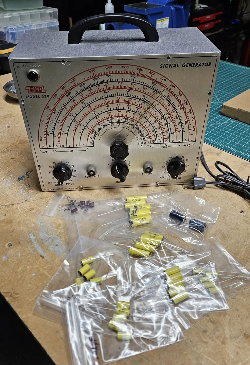
A vacuum tube signal generator, about 60 years old, with new capacitors, new connectors and a clean signal again.
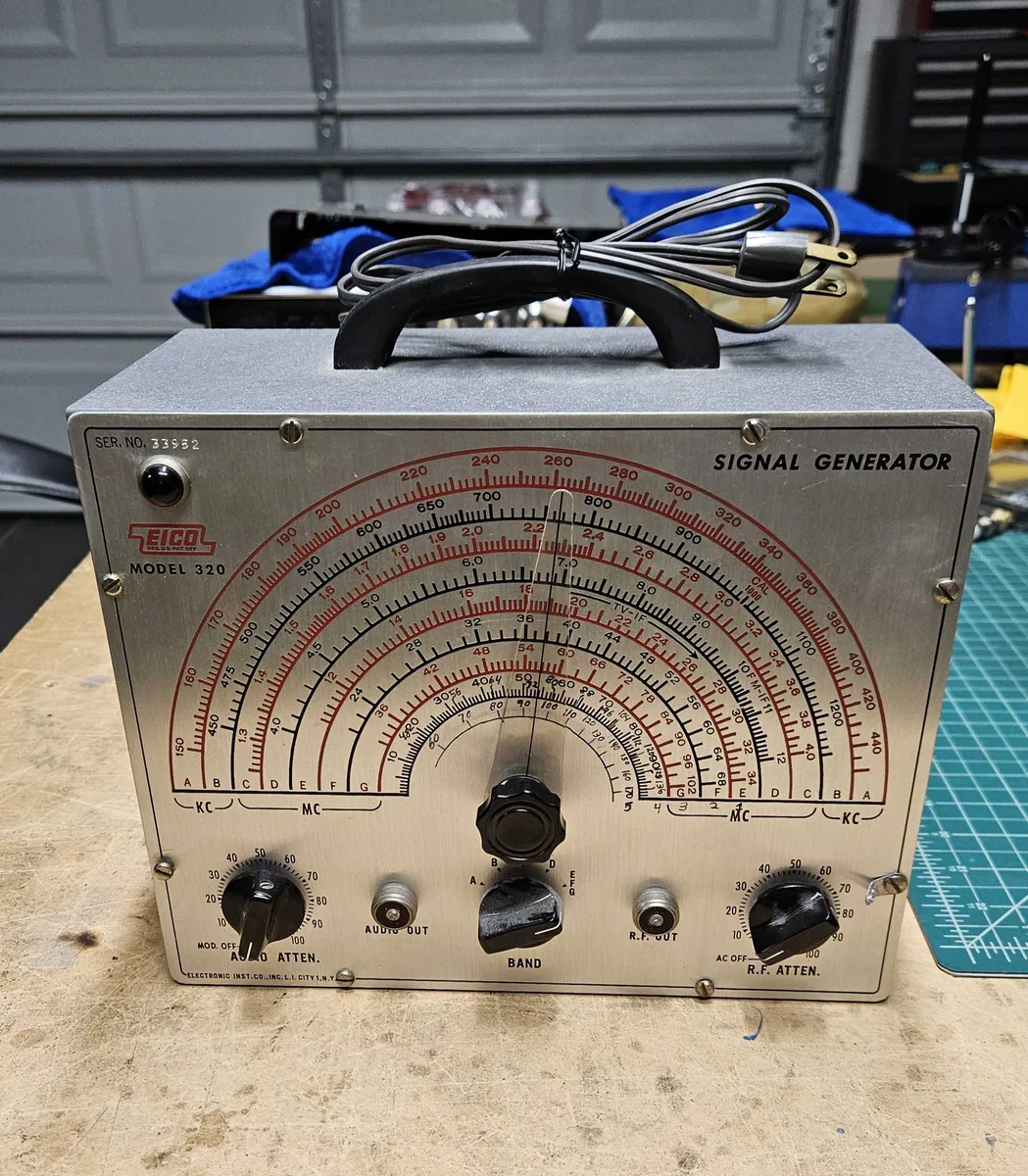
This relic is an EICO Model 320 Signal Generator. EICO stands for Electronic Instrument Company. A signal generator makes a steady radio signal at whatever frequency you set on its dial. You feed that signal into a radio to test it or to tune it up.
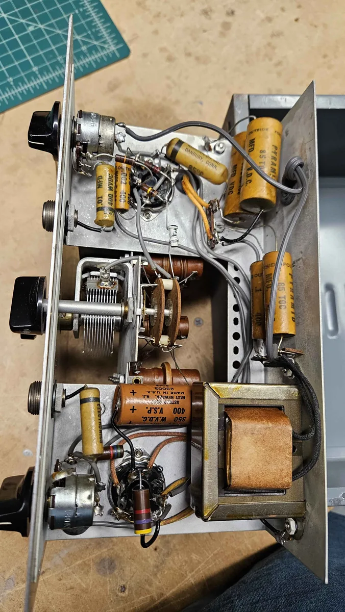
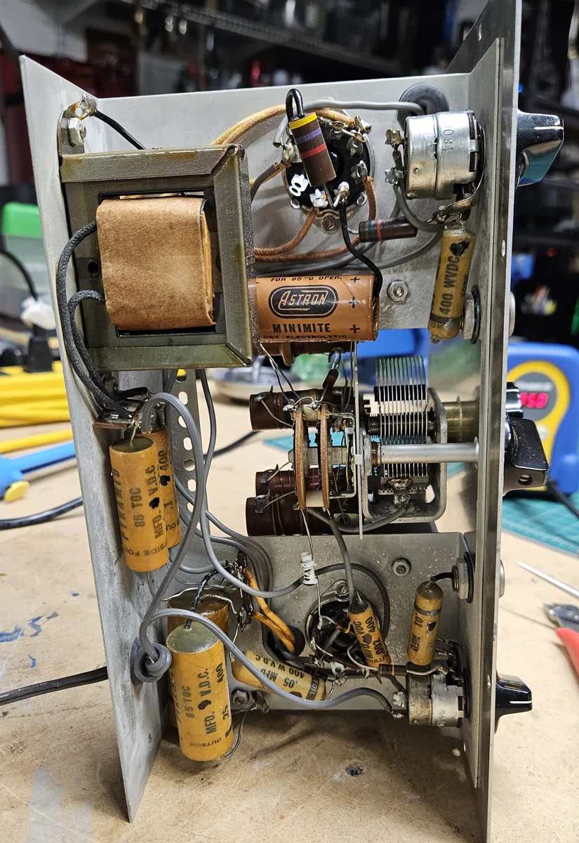
It uses 2 vacuum tubes and wax paper capacitors. I had never actually seen wax capacitors until now. It is always fun opening these old pieces of equipment up. In the winter of 2025 I replaced the old capacitors and the connectors, then calibrated and tested it.
1. A look inside
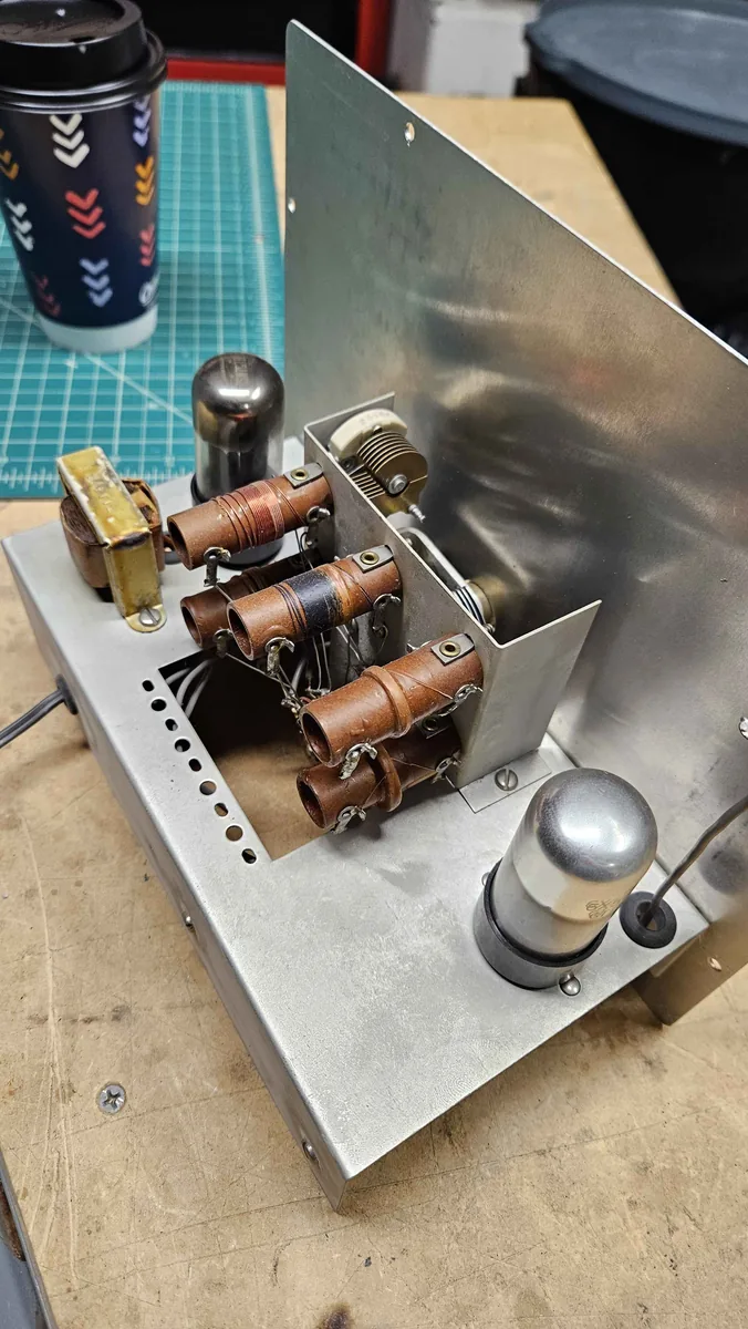
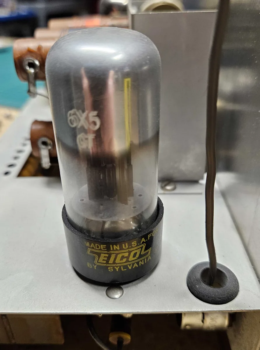
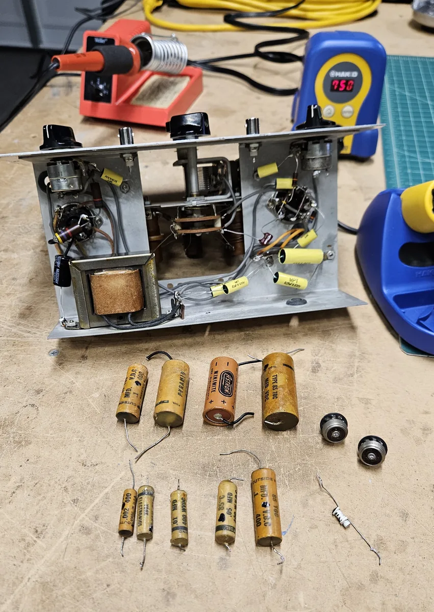
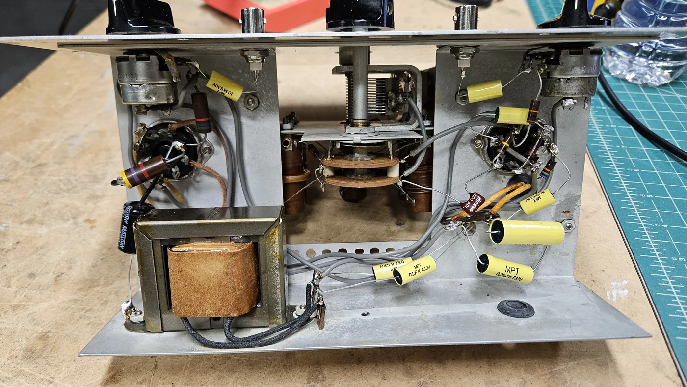
One tube, a 6SN7, does the real work. Half of it makes the radio signal and the other half makes a 400 Hz audio tone. The second tube, a 6X5, is the rectifier in the power supply. The dial starts at 150 kHz and is split into seven bands, lettered A through G, with markings up to 102 MHz. The brown coils set the band, and the yellow parts are the wax paper capacitors.
2. New capacitors
I replaced all of the old wax paper capacitors. In went 8 metallized polypropylene film capacitors, 1 electrolytic and 1 mica. I didn't replace any resistors, as all of the resistors tested within 5 to 10% of their values.
3. BNC connectors
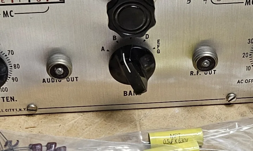
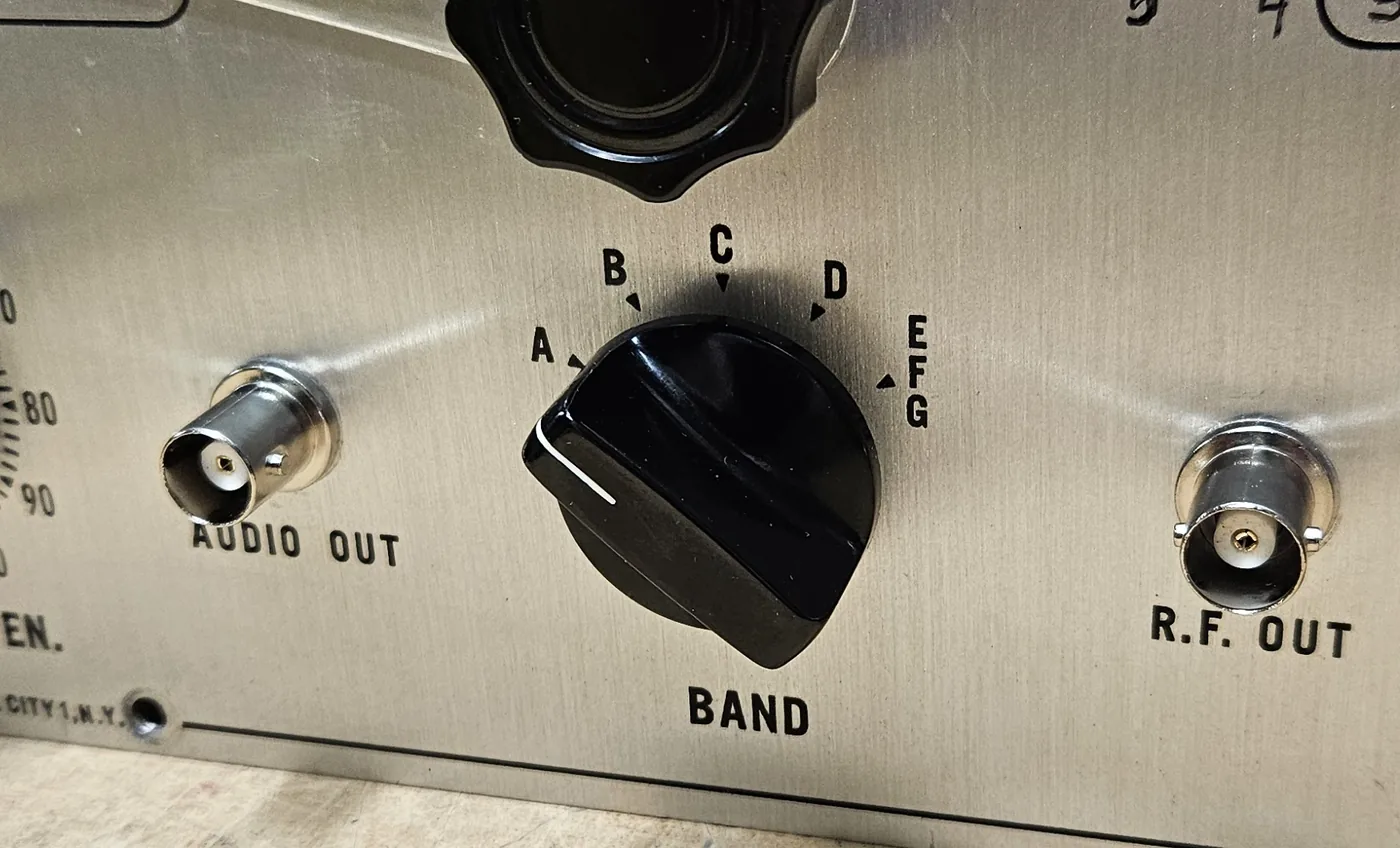
I also replaced the old screw-on panel "mic" connectors with more modern 50 ohm BNC panel connectors, so standard test cables plug straight in.
4. A mystery part
I believe this signal generator was slightly modified some time in the past. The original schematic and parts list call for a 50 picofarad mica capacitor, which wasn't there. Another component was in its place: a small white cylinder.
I suspect it was done to add or change some of the higher frequencies. On the dial face you can see new frequencies written in by hand.
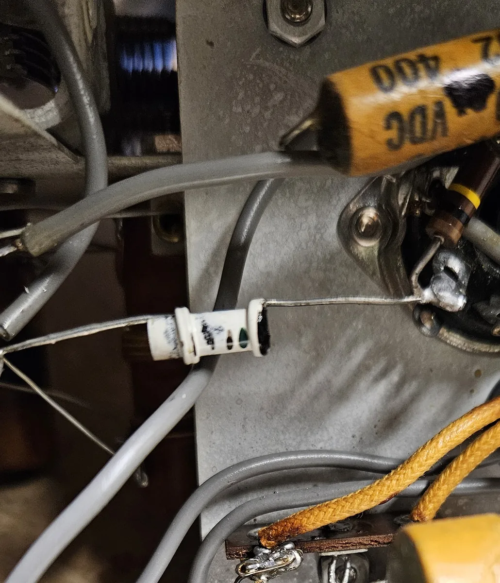
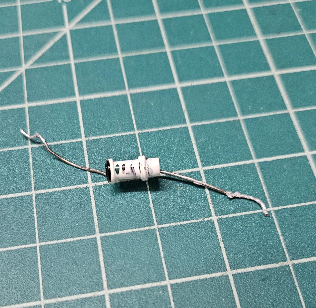
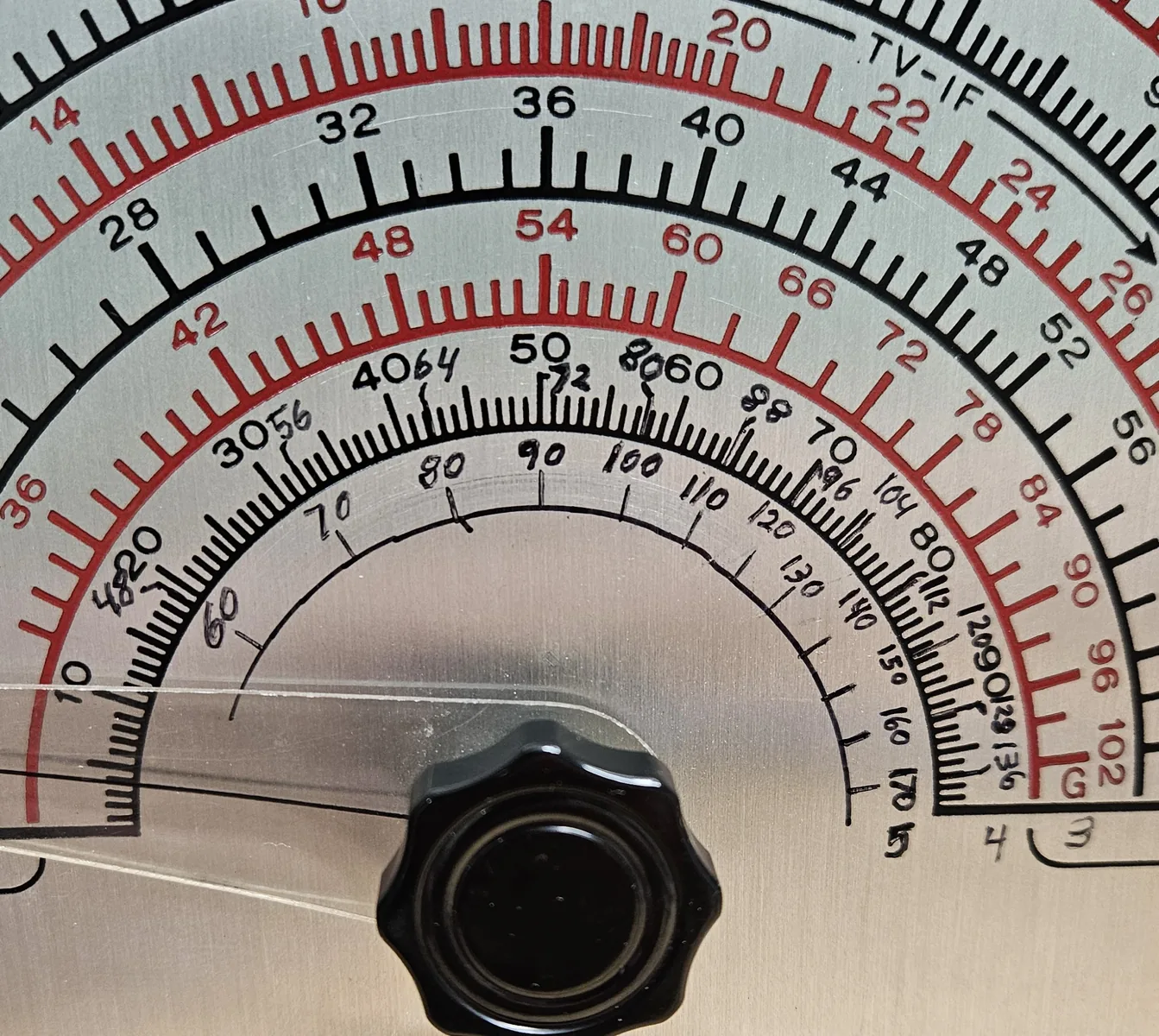
Peter, KF7PSM, thought the white part may be an inductor, and that it looks like someone wanted to get up to 2 meter frequencies. With older equipment like this, the higher you go the more stability you lose, so that was probably as high as they could reasonably get.
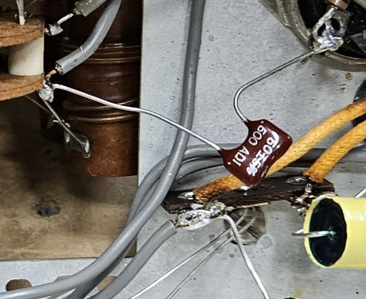
Regardless, I replaced it with what the schematic originally called for, a 50 picofarad mica capacitor.
5. Calibration and testing
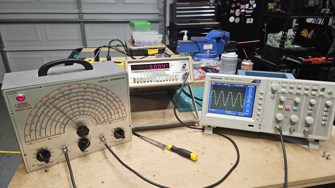
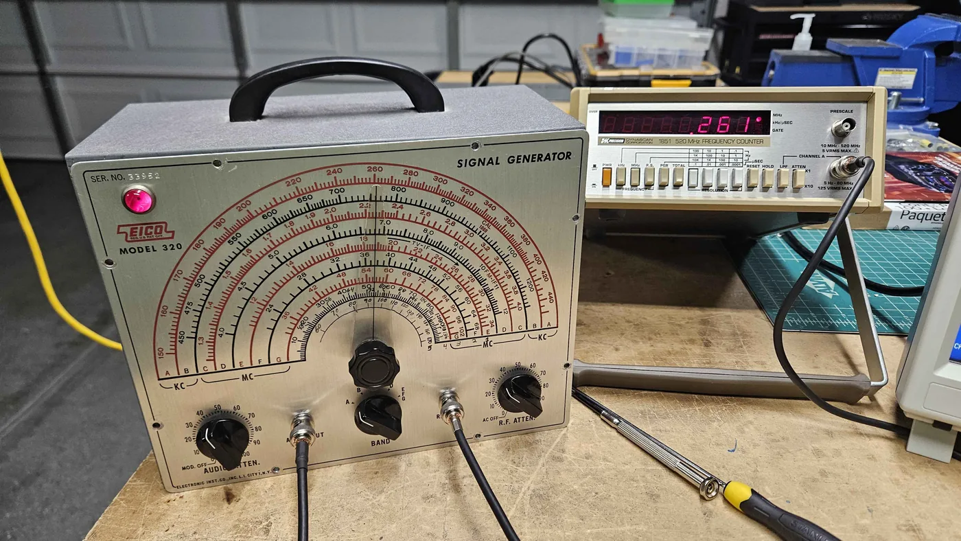
The next day I calibrated and tested it. It supplies a fairly accurate and clean signal for being about 60 years old. The oscilloscope shows the audio output, which is close to the standard 400 Hz, as a clean sine wave. On the frequency counter I checked radio signals at 5 MHz, 10 MHz and 260 kHz.
Back to work
The Eico has already earned its keep. I used it to align my Realistic DX-160 shortwave receiver.
Parts
| Qty | Part | Type |
|---|---|---|
| 1 | 50 pF | Mica |
| 1 | 0.002 µF (2 nF) | Film |
| 2 | 0.01 µF | Film |
| 1 | 0.05 µF | Film |
| 2 | 0.1 µF | Film |
| 1 | 0.25 µF | Film |
| 1 | 0.5 µF | Film |
| 1 | 16 µF or greater, 350 V | Electrolytic |
| 2 | 50 ohm BNC female, panel mount | Connector |
The film capacitors are metallized polypropylene, rated 400 volts or more.