
Realistic DX-160 Shortwave Receiver
A 1970s Radio Shack solid-state shortwave receiver, bought from a ham who was downsizing, then aligned and given a proper antenna jack, with plenty of help from the local ham breakfast crowd.
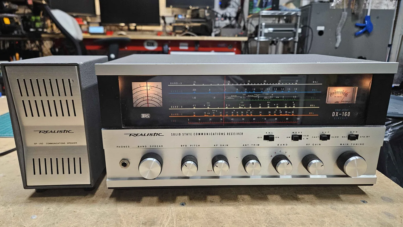
The Realistic DX-160 was Radio Shack's solid-state shortwave and AM broadcast communications receiver. I bought mine from a ham who was downsizing. It needed a little work, and some very knowledgeable people helped me learn how to do it. This page follows that: the alignment, a better antenna connection, and the test gear that came along.
I run it from my MLA-30 magnetic loop. The same loop also feeds my SDR through an active splitter, so both radios can listen to the same antenna at once.
Listening
On March 8, 2026 I was tuning around "old school" and heard WWCR, the Overcomer Ministries station out of Nashville, Tennessee, on 5935 kHz.
Alignment
At a breakfast meetup of the Henderson Amateur Radio Club (HARC), Larry, K7MLG, gave some of us a primer on aligning a radio. I took that home and aligned the DX-160 that same afternoon, both the IF and the RF stages, using an Eico 320 signal generator (made sometime in the 1950s or 60s), an oscilloscope and a sensitive digital voltmeter.
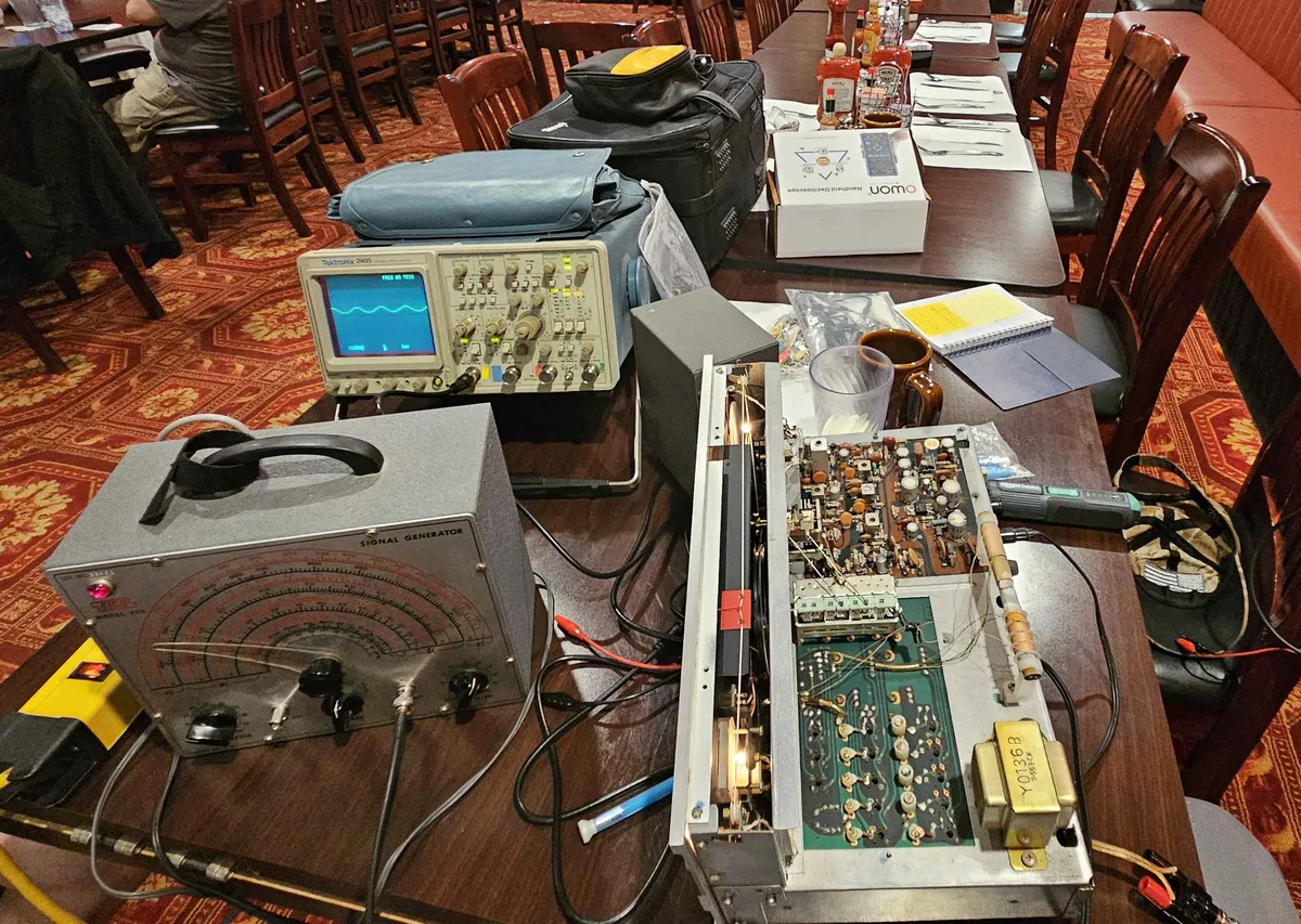
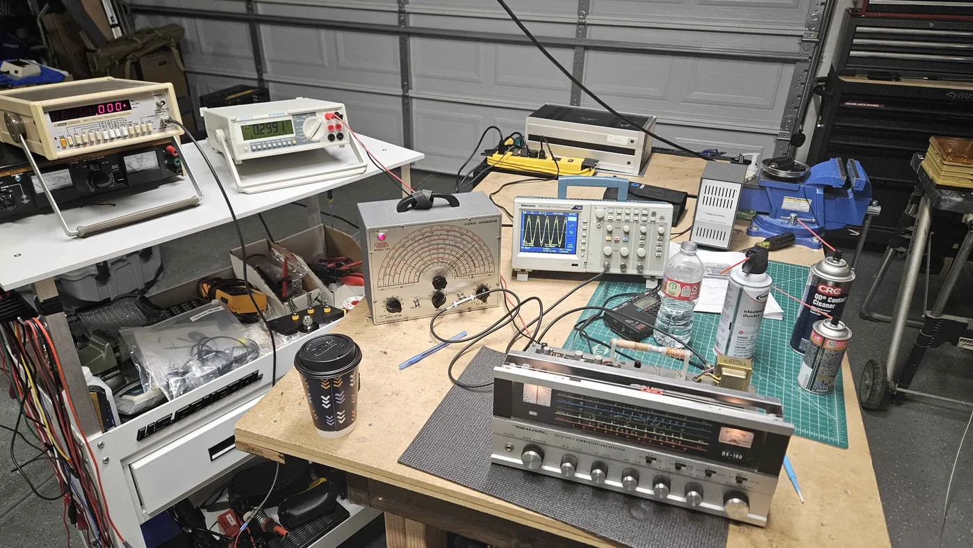
Two short videos I made while doing it:
A proper antenna jack
The DX-160 only came with screw terminals for the antenna. To connect my 50-ohm mag loop I had been using a DIY BNC-to-screw-terminal adapter, and that created an impedance mismatch. So on March 25 I decided to install a panel-mount BNC connector with a 9:1 balun.
The BNC fit in an unused factory hole hidden behind the serial number sticker. I warmed the sticker with a heat gun, peeled it off, and moved it to the bottom panel. The connector fit almost perfectly in the hole.
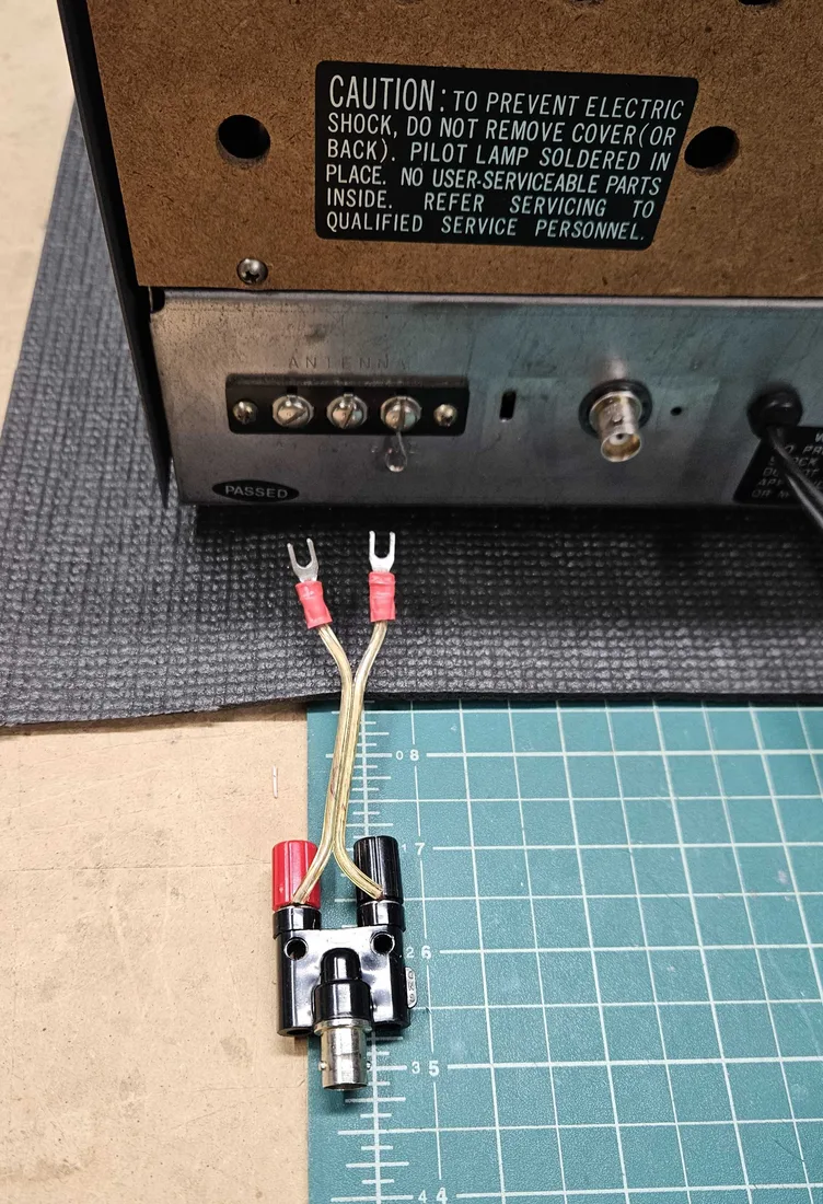
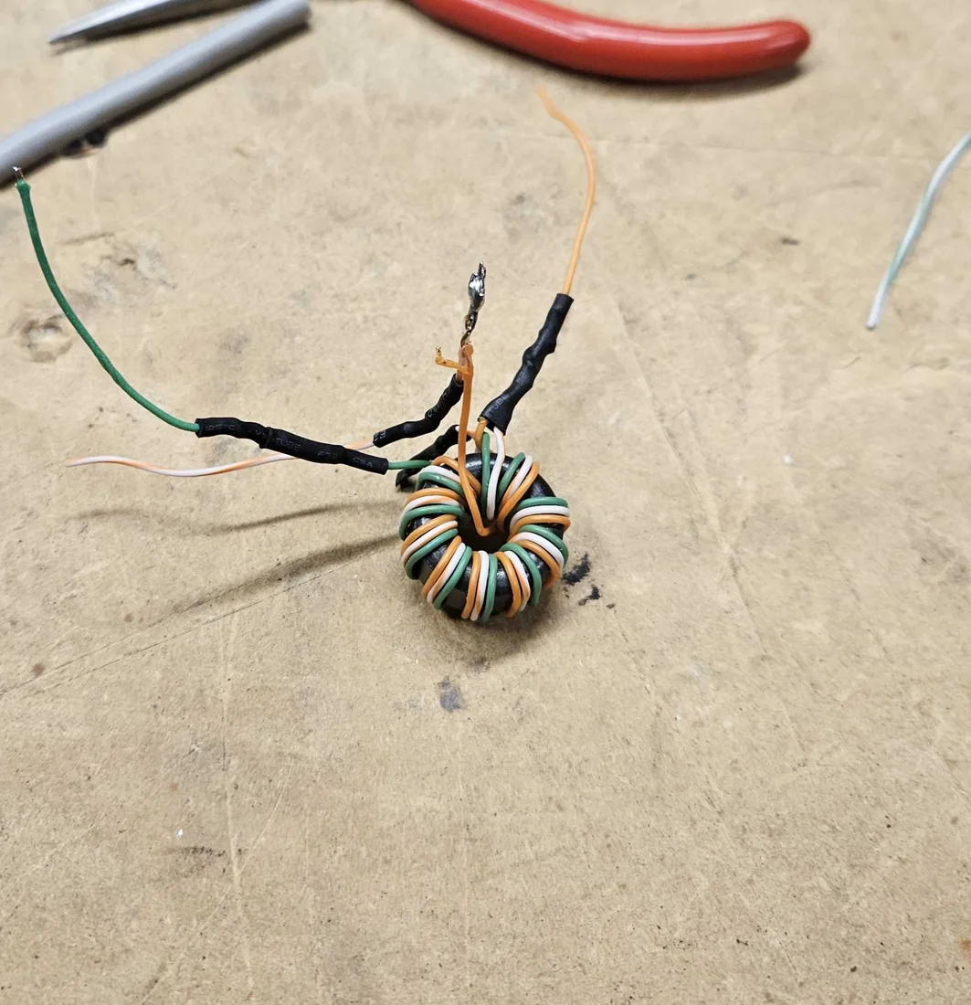
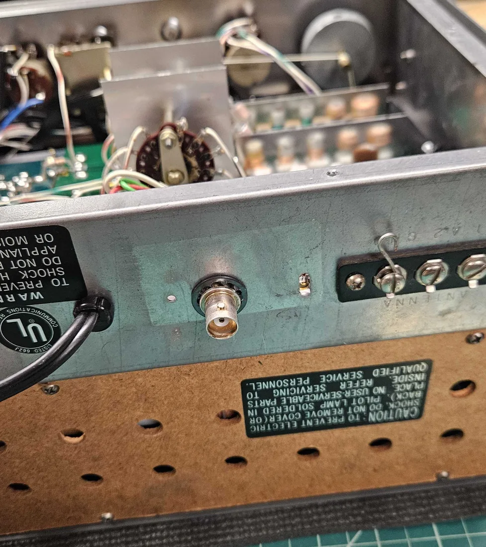
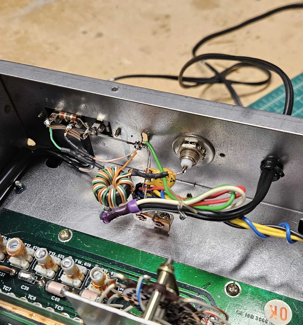
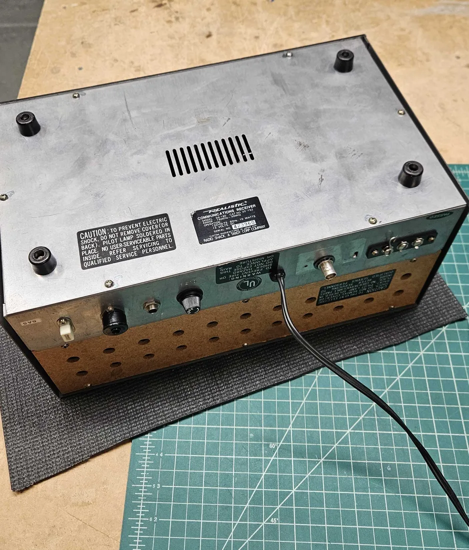
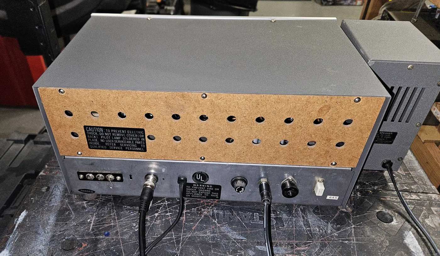
With the retrofit done, that same evening I tuned to WWV, the U.S. time-signal station, on 5000 kHz. It came in strong that night:
A Heathkit VTVM
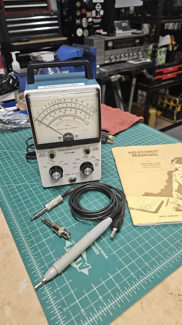
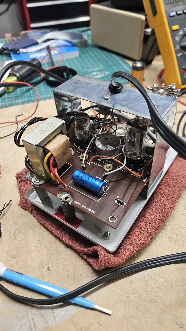
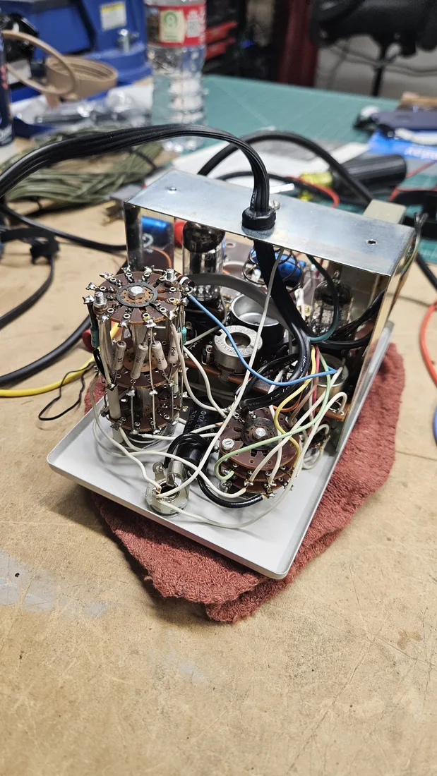
When I aligned the DX-160 I didn't have a vacuum tube voltmeter (VTVM), so I got by with a sensitive enough digital voltmeter. Then someone kindly gave me a Heathkit VTVM (Model IM-5218) from the late 80s, in pristine condition. I took it to the Tuesday breakfast, where K7MLG helped me give it the once over.
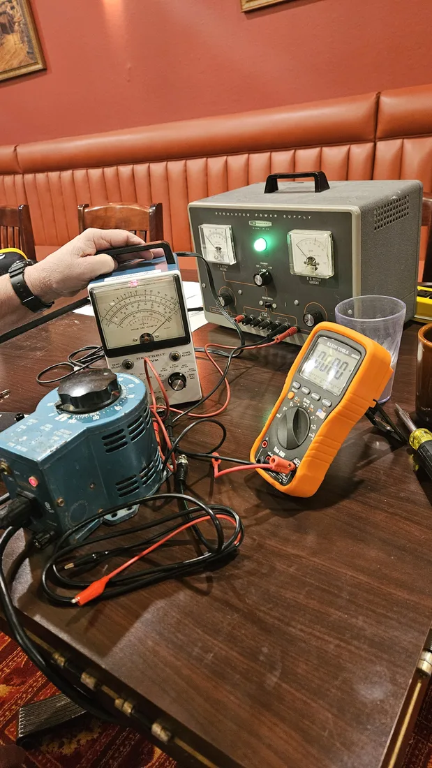
It only needed a slight calibration, which I finished on June 12.
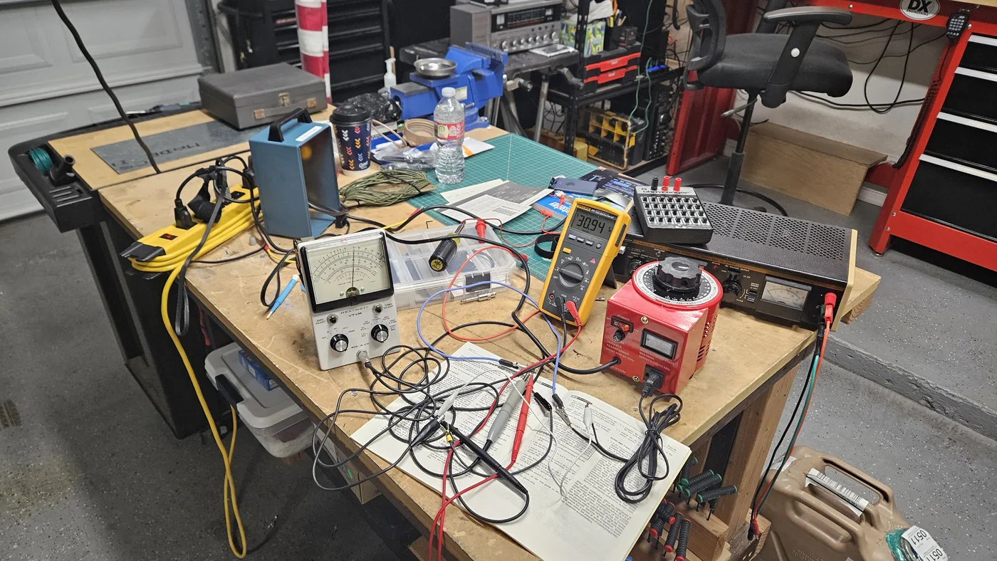
The probe
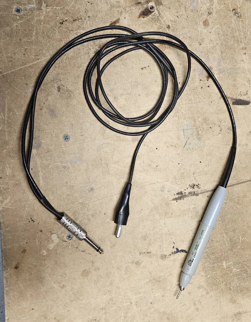
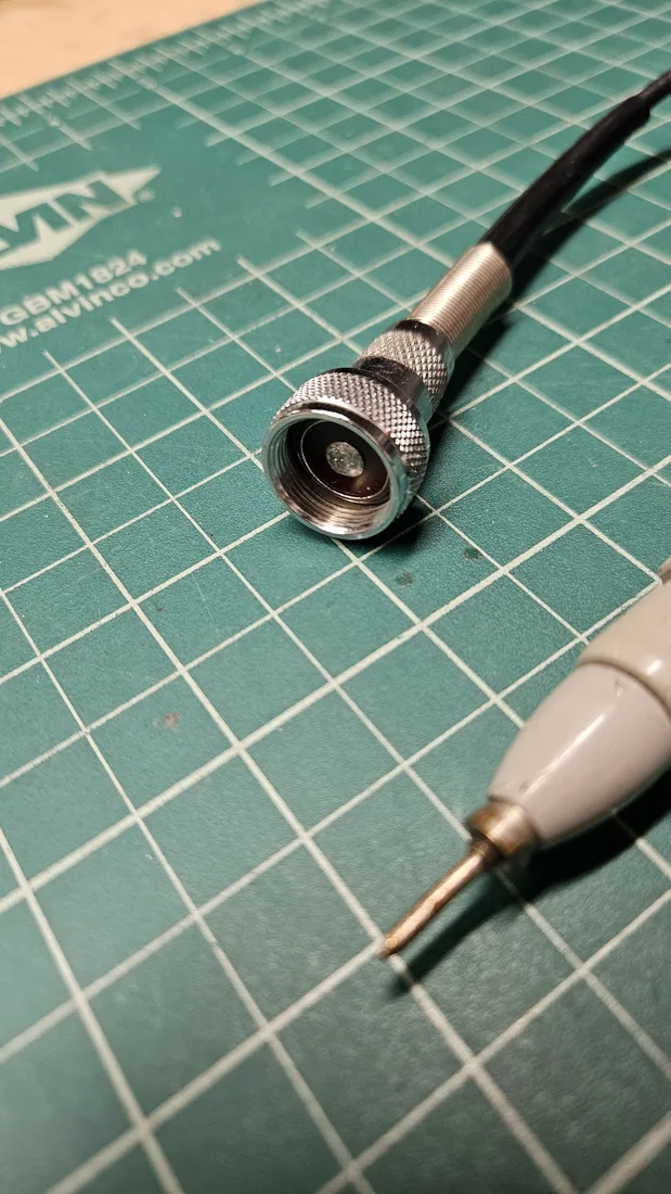
The meter also needed a probe. Larry, K7MLG, donated a used RCA WG-289 probe for the project. RCA made it for its own meters, so it had to be retrofitted for the Heathkit: I replaced its screw-on connector with a ¼-inch audio plug and added a ground wire with an alligator clip.
It's common to replace the meter's ¼-inch jack with a BNC connection. But the VTVM was in such great condition that I wanted to keep its original form.
Why a VTVM?
A vacuum tube voltmeter is designed to have a very high input impedance when testing circuits. That means the meter doesn't load the circuit and change what it's measuring, which is why it's generally preferred when aligning AM radios.