
LoRa APRS Tracker
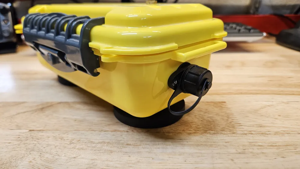
N7WDZ-21: a battery-powered LoRa APRS tracker in a waterproof case, with a plug-in solar panel for longer trips
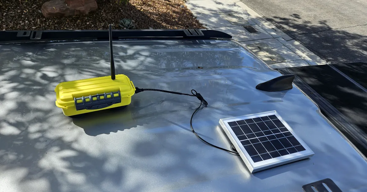
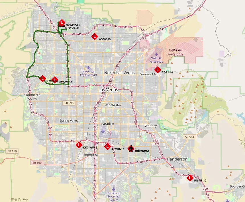
APRS trackers send their GPS position over the radio every so often, so their travels show up on maps like aprs.fi. This one does it with LoRa, a long-range, very low-power radio mode, on the 433 MHz (70 cm) band. Its packets are picked up by LoRa iGates, including my own N7WDZ-25, and passed on to the APRS internet network.
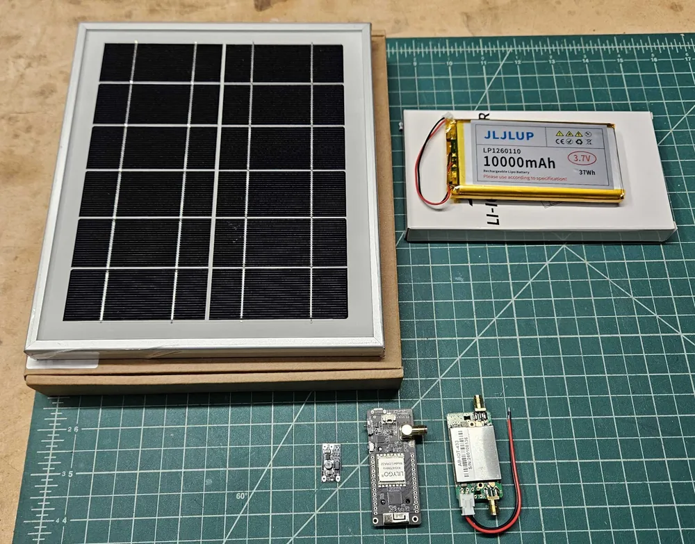
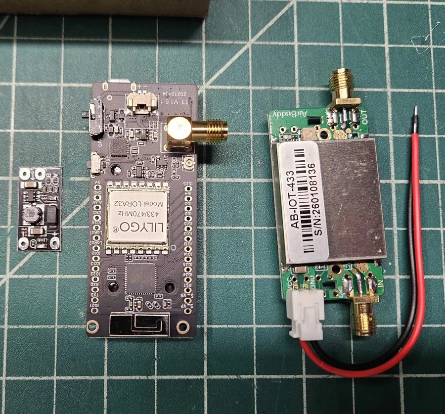
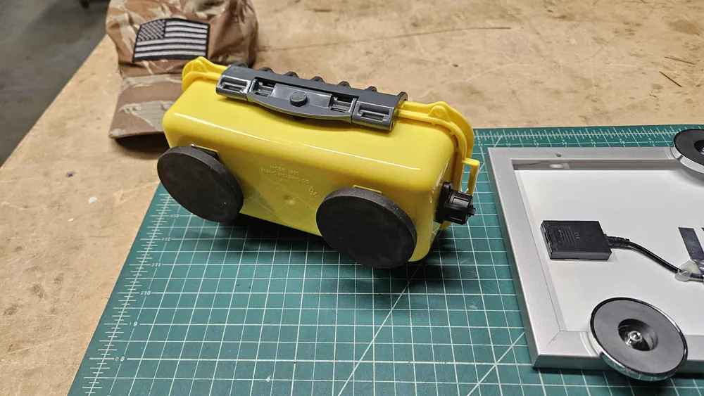
Inside the yellow case is a LILYGO LoRa32 board running the free CA2RXU LoRa APRS Tracker firmware, a GPS module, a two-way booster that raises the transmit power to about 2.3 watts, and a 10,000 mAh battery. The firmware uses smart beaconing: it sends more often while driving and on every turn, and only now and then while parked, which keeps the track accurate without wasting battery. For multi-day trips a small 6-volt solar panel plugs into a waterproof port on the side.
The firmware holds three profiles, each with its own SSID and its own beacon settings: fast, medium and slow. The fast profile gives the most detailed track, and the slow one saves the most battery on long trips. I can switch between them from the tracker's menu with the select button. Right now it's running as N7WDZ-21.
Video
How it's wired
The LILYGO board can charge the battery through its USB port, and it powers the GPS from its 5-volt pin. The booster needs more current than the board can supply, so it gets its own boost converter that raises the battery's 3.7 volts to a steady 5 volts. At 5 volts the booster puts out about 2.3 watts, compared with 1.4 watts straight off the battery.
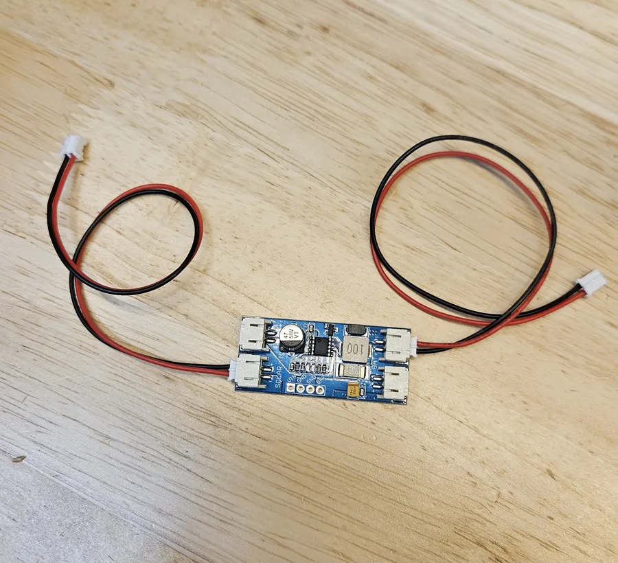
The solar panel started out built into the case, but it made the box much bigger than it needed to be, and most trips don't need it. Now the panel and its CN3791 MPPT charger are one separate unit, with the charger sealed in heat-shrink right on the cable, that plugs into the waterproof charge port on the side of the case.
The build
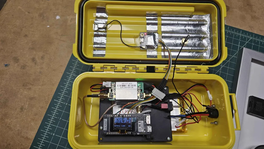
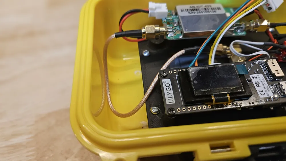
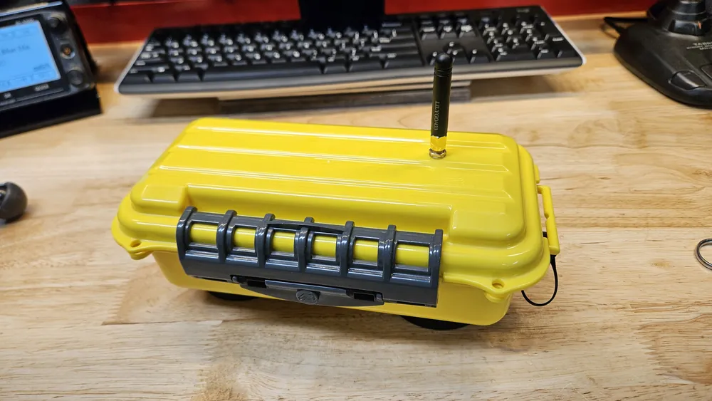
On the map
Parts
- LILYGO LoRa32 T3 v1.6.1, 433 MHz: ESP32 with a LoRa radio, OLED screen and a built-in battery charger
- AirBuddy AB-IOT-433 two-way LoRa booster: about 2.3 watts transmit at 5 volts, switches between receive and transmit on its own
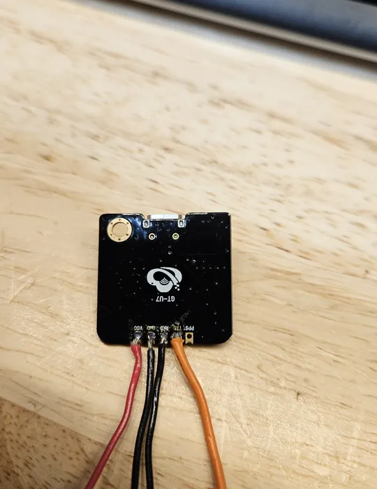
- GT-U7 GPS module (u-blox NEO-6M compatible)
- 10,000 mAh 3.7 V LiPo battery with a built-in protection board
- AITRIP mini boost converter, set to 5 volts, for the booster only
- Master on/off switch and a push button
- Waterproof case, 18.5 × 8 × 6 cm, with a 3D-printed mounting plate
- Solar accessory: 6 V 5 W solar panel and CN3791 MPPT solar charger (6-volt version), with an 18 AWG M16 two-pin waterproof connector
Battery life
Estimated time on a full charge with no sun. Driving uses more power because the tracker transmits much more often.
| Use | Average draw | Runtime |
|---|---|---|
| Parked (a beacon every 15–30 min) | about 105 mA | about 4 days |
| Driving (a beacon every 30–60 s) | about 145–155 mA | about 2½ days |
In full sun the 5-watt panel puts back up to about 0.8 amps.
Wiring the GPS and button
The T3 v1.6.1 has no GPS or user button of its own, so both are added by hand. These pins match the firmware's "LoRa32 v2.1/1.6.1 + GPS (DIY)" board setting.
| From | To LILYGO pin | Notes |
|---|---|---|
| GPS VCC | 5V | Works on battery alone, no USB needed |
| GPS GND | GND | |
| GPS TXD | GPIO 34 | The board receives GPS data here |
| GPS RXD | GPIO 12 | A boot "strapping" pin; first suspect if boot problems ever show up |
| Push button | GPIO 15 + GND | Select button for screens, the menu and switching profiles |
Lessons learned
- The board's on/off switch isn't enough. It turns off the LILYGO board and the GPS, but the booster stays powered through the boost converter. A master switch in the battery lead now turns everything off. It also cuts charging, so the switch has to be on to charge.
- Turn the GPS on in the firmware. The tracker settings include a
disableGPSoption; it has to befalseor the firmware ignores the GPS module. - Check battery polarity. Some LILYGO boards have the battery connector reversed, so check before plugging in, and label the charge port.
- Add a button. The T3 v1.6.1 only has a reset button. The firmware expects a select button, so a push button goes between GPIO 15 and ground.
- Slow the beacons down on long drives. A fast rate of 90–120 seconds instead of 30–60 means fewer high-power transmissions, and the track still looks good because the firmware beacons on every turn. The slow profile is there for exactly that.
Links
Credits
The LoRa APRS Tracker firmware is by Ricardo Guzman, CA2RXU, and is free and open source. Thanks to the LoRa APRS community on Discord for confirming the GPS and button pins. The map above is from the LoRa APRS map by EA2RCF Radioclub Foronda.