
PicoTerm: Connecting a CoCo 3 to a Pocket Pico
A terminal program written for one job, and a home-built cable, so a Tandy Color Computer 3 can talk to a Pocket Pico packet TNC with no setup at all.
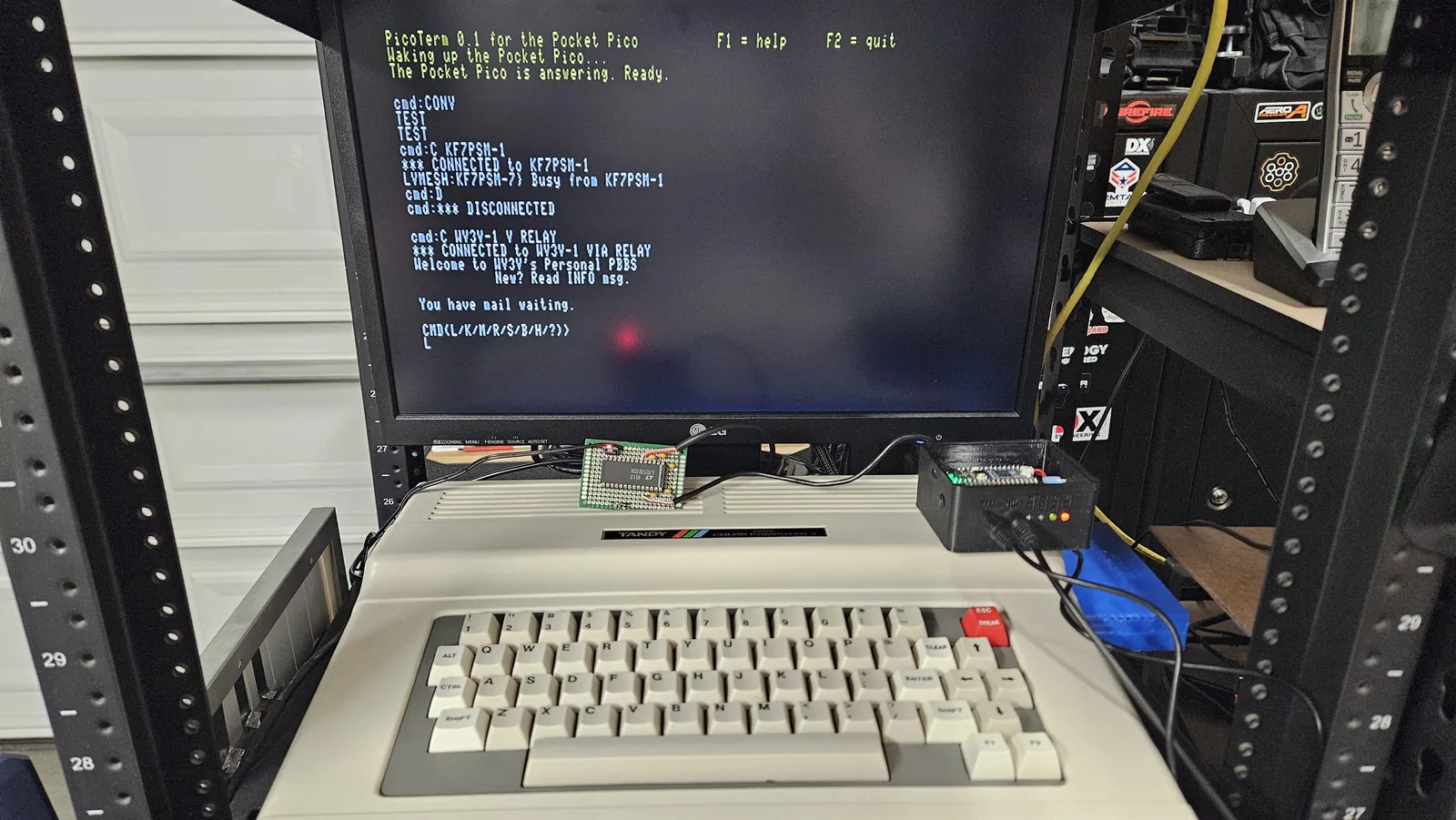
My Tandy Color Computer 3 already made it onto packet radio with a
Heath HK-21 Pocket Packet and the terminal programs VTerm and AutoTerm. They work, but every session started
with settings screens: speed, data bits, parity, duplex. I wanted something simpler: put in the disk, type one
command, and be at the TNC's cmd: prompt.
The TNC this time is a Pocket Pico, the Raspberry Pi Pico based packet TNC by Peter, KF7PSM. It emulates the HK-21, so to the CoCo it looks just like the real thing. Two pieces were needed: a program for the CoCo, and a cable between the two.
1. PicoTerm, the program
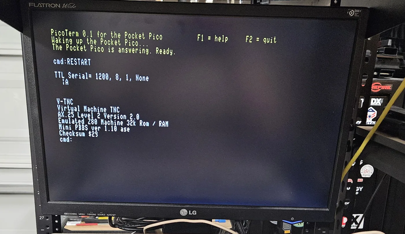
PicoTerm is a small terminal program written in 6809 machine language. It only does one thing: talk to a Pocket Pico at 1200 baud, 8 data bits, no parity, 1 stop bit, on an 80-column screen. There is nothing to set up. I worked it out with the help of an AI assistant, Claude, which wrote the assembly code and tested it in an emulator.
- It wakes up the Pico by itself. On start it sends Ctrl-C and ENTER. If
cmd:comes back, it is ready. If not, it sends a*every 0.7 seconds, because the HK-21 ROM sets its speed from a*. After about 9 seconds with no answer it says to check the cable and power. - Nothing gets lost while the screen scrolls. The CoCo's serial port is "bit-banger": the processor itself turns every bit on and off. PicoTerm uses a timer interrupt that checks the line 4,800 times a second, so it receives and sends at the same time and keeps up even while the screen is moving.
- Colors: text from the Pico is white; PicoTerm's own messages are yellow.
- F1 shows the help on screen, and F2 goes back to BASIC.
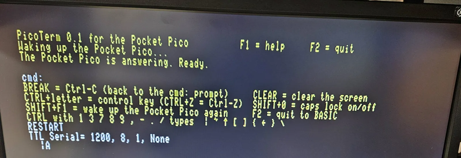
The keys, for a CoCo keyboard that has no ESC, no Ctrl-C and no curly brackets:
| CoCo key | What it does |
|---|---|
| BREAK | Ctrl-C (back to the cmd: prompt) |
| CLEAR | Clear the screen |
| CTRL + letter | Control key (CTRL+Z = Ctrl-Z) |
| Left arrow | Backspace |
| SHIFT+0 | Caps lock on/off (starts on) |
| F1 | Help on screen |
| SHIFT+F1 | Wake up the Pocket Pico again |
| F2 | Quit to BASIC (press Y to confirm) |
Characters the CoCo keyboard doesn't have are typed with CTRL plus a key:
| CTRL + | 1 | 3 | 7 | 8 | 9 | , | - | . | / |
|---|---|---|---|---|---|---|---|---|---|
| Types | | | ~ | ^ | [ | ] | { | _ | } | \ |
The CoCo's font shows ^ as an up arrow and _ as a left arrow. The
right characters are still sent.
2. Loading it from the CoCo SDC
PicoTerm comes as one disk image, PICOTERM.DSK, holding a short BASIC launcher and the machine
language program. I keep it on its own SD card in the CoCo SDC
cartridge. From the BASIC OK prompt, mount the disk image and run it:
DRIVE 0,"PICOTERM.DSK"
RUN"PICOTERM"
The launcher switches to the 80-column screen, loads the program and starts it. Pressing F2 and then Y goes back to BASIC with a reminder of how to start it again. The disk image works from a real floppy too.
3. Why a cable with a chip in it
The two ends don't speak the same voltages. The Pocket Pico's serial jack is 3.3-volt logic (TTL). The CoCo 3's 4-pin DIN serial port uses RS-232 levels, which swing to about plus and minus 12 volts. Wiring them straight together would damage the Pico. A level converter chip in the middle translates in both directions.
| Pocket Pico 3.5 mm jack | Signal | CoCo 3 4-pin DIN | Signal |
|---|---|---|---|
| Tip | Pico receive | Pin 2 | CoCo receive |
| Ring | Pico transmit | Pin 4 | CoCo transmit |
| Sleeve | Ground | Pin 3 | Ground |
| Pin 1 | Carrier detect (not used) |
4. The first test cable
The first live test used a test cable donated by Peter, KF7PSM, built around an ICL232, a 5-volt RS-232 converter chip, with a 7805 regulator and four capacitors on a small Radio Shack board. I reworked it for this job: a 4-pin DIN plug on the RS-232 side, a 3.5 mm plug on the logic side, and a two-resistor divider (2k and 3.3k) so the chip's 5-volt output comes down to a level that is safe for the Pico.
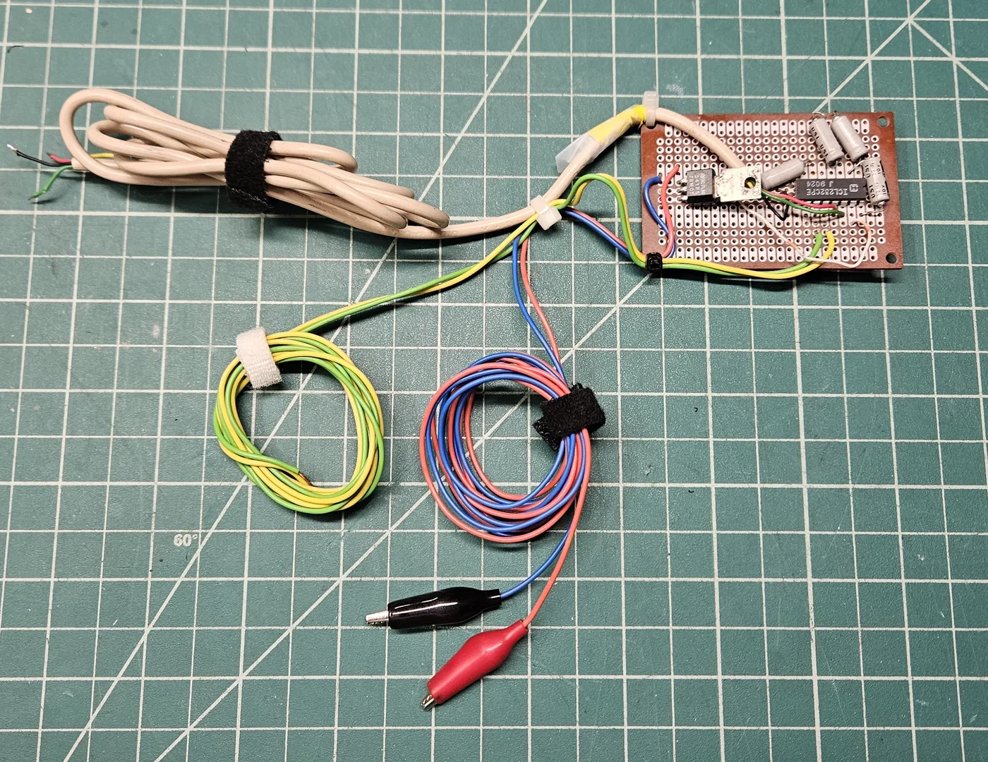
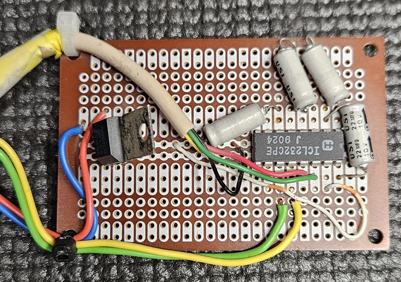
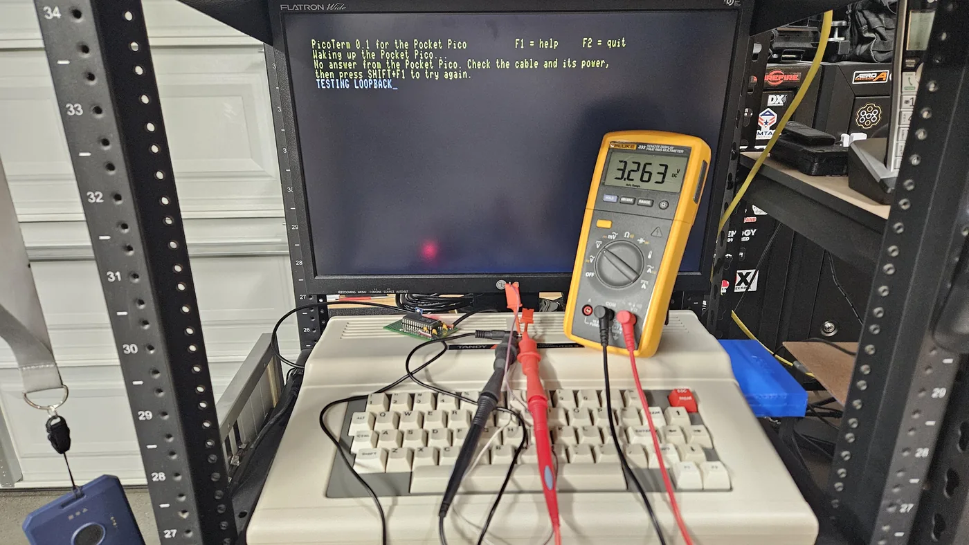
The first try got no answer, but a loopback test proved the cable and the CoCo were fine (more on that
below). The catch was on the Pico side: it was still set to 115200 baud (see section 8). Once that was fixed,
the cmd: prompt came right up.
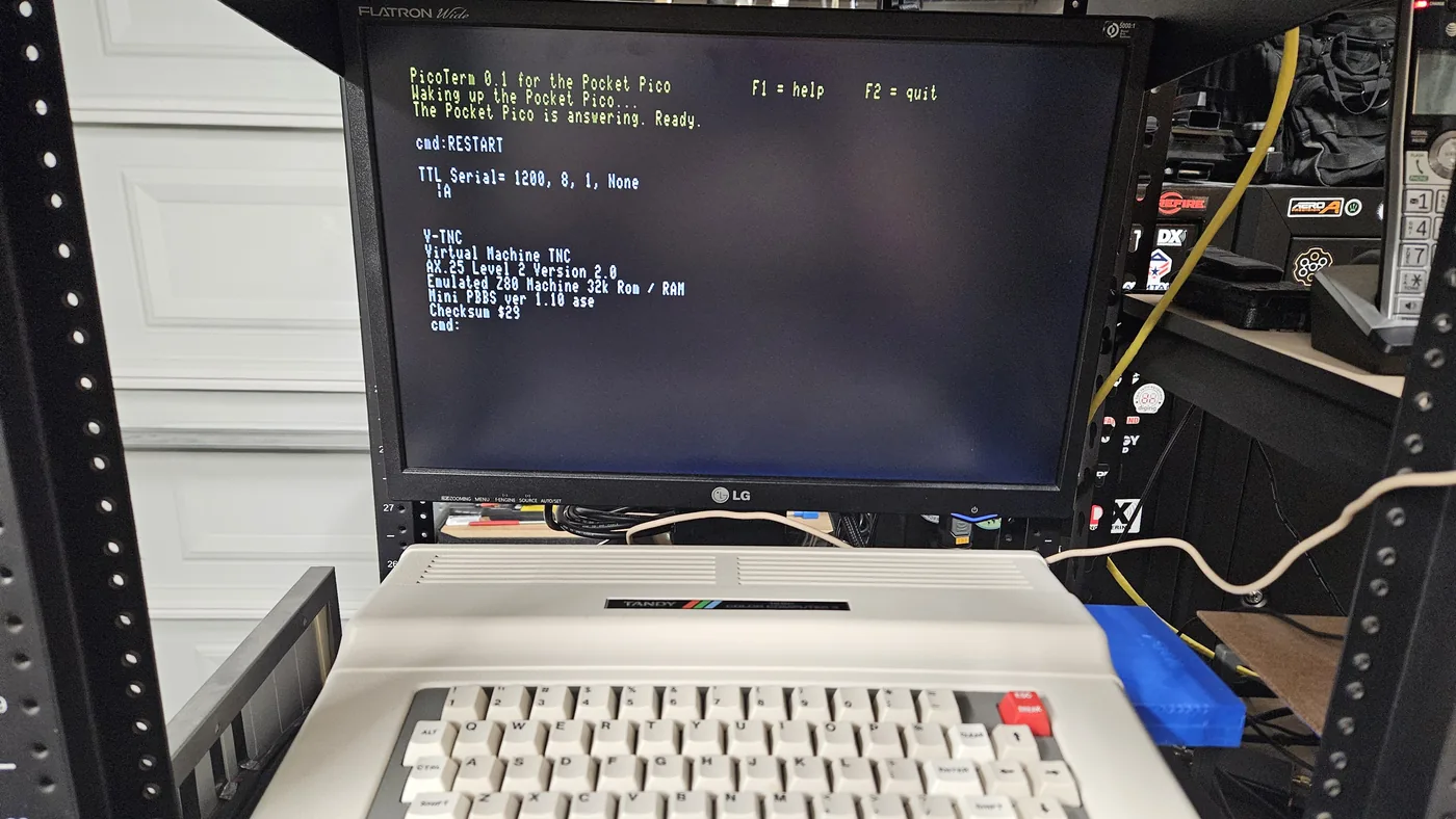
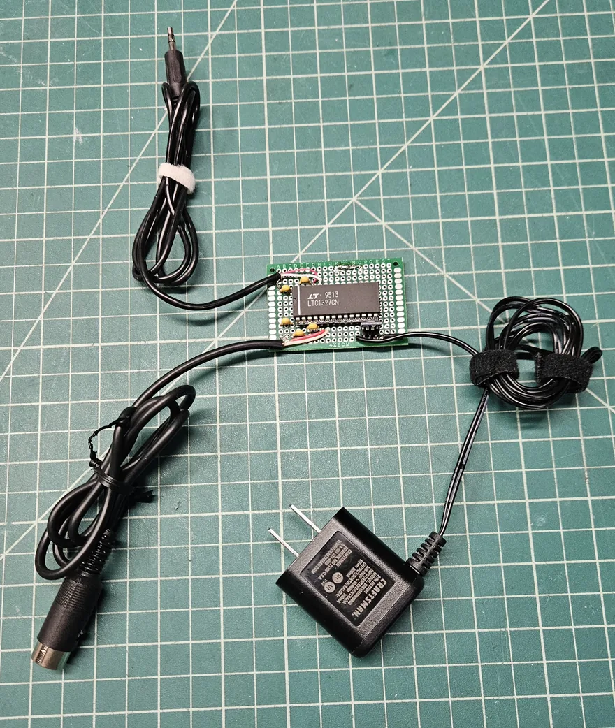
5. The finished cable: an LTC1327 on perfboard
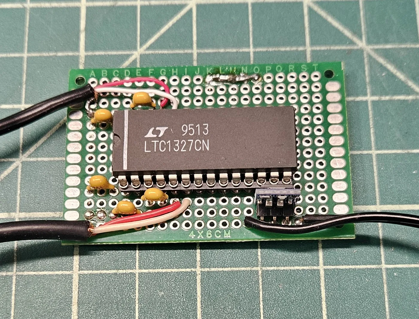
For the permanent cable I used an LTC1327 from Linear Technology, another donation to the cause from Peter, KF7PSM. It runs on 3.3 volts, so its logic output can never go above what the Pico can take, and no divider resistors are needed. Its RS-232 outputs swing about plus and minus 5 volts, enough for the CoCo, and its inputs take the CoCo's plus and minus 12 volts without trouble.
- LTC1327CN, a 28-pin chip, in a socket
- Five 0.1 µF ceramic capacitors for the chip's built-in charge pump
- AMS1117 3.3-volt regulator board, fed by a 5-volt, 600 mA wall adapter
- 4 × 6 cm perfboard
- 3.5 mm plug for the Pico, 4-pin DIN plug for the CoCo
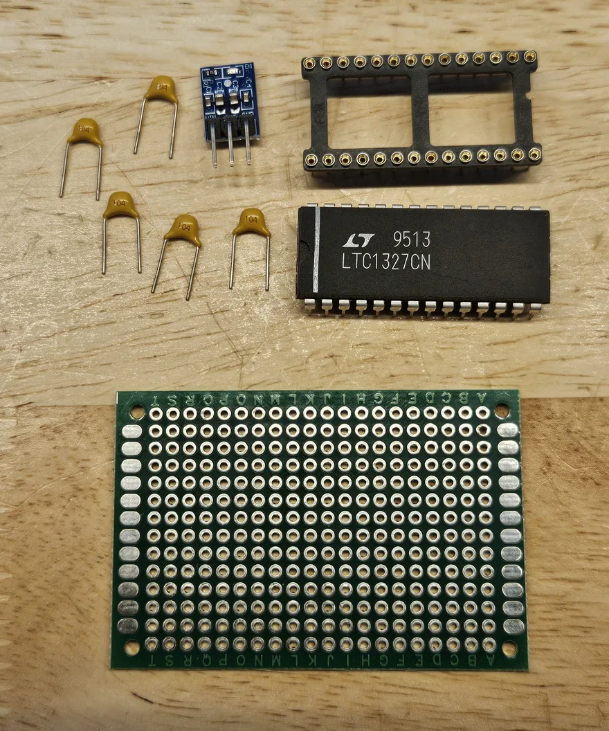
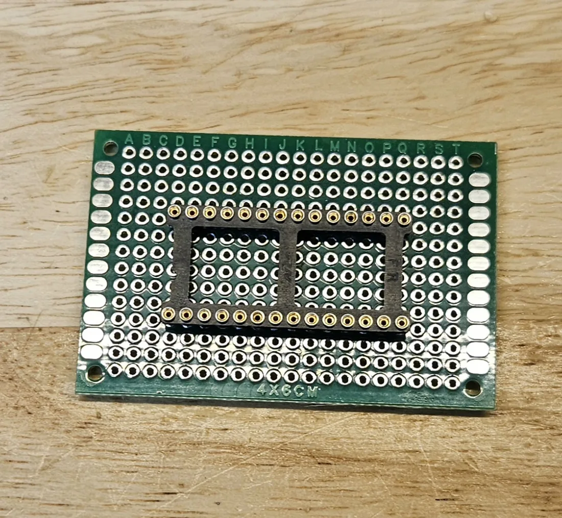
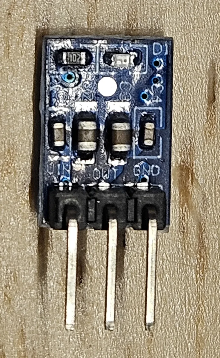
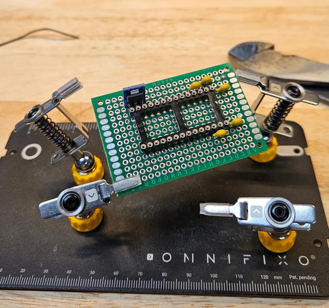
I built it one step at a time, checking with a meter after each one: socket, capacitors, regulator, the 3.3-volt and ground wiring, then the two plugs. The chip went in last, only after the power checks passed. With the chip in: 3.26 volts from the regulator, plus 5.3 and minus 5.2 volts from the charge pump, and minus 5.19 volts on the CoCo's receive pin at idle, all as expected.
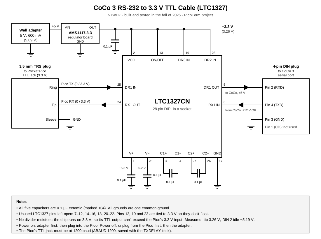
Loopback test: before plugging into the Pico, I jumpered the 3.5 mm plug's tip to its ring. Anything typed in PicoTerm then goes out through the cable and comes straight back, so letters showing on the screen prove the CoCo and both directions of the cable work. It is also the first thing to try if PicoTerm ever gets no answer.
6. A 3D-printed case
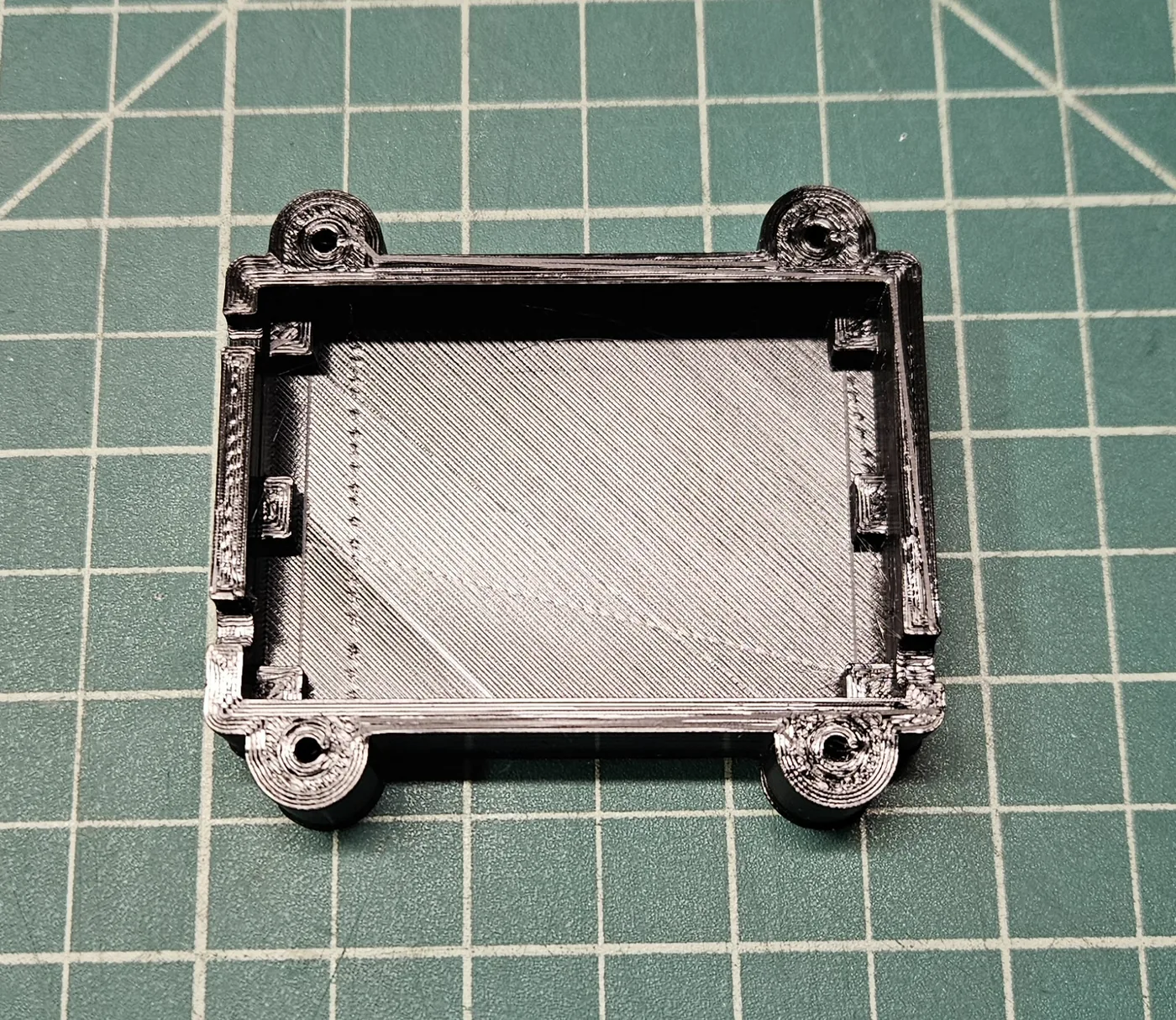
The board got a case designed in OpenSCAD from my measurements of the finished board, and printed on my Flashforge 3D printer. A first test print in PLA fit perfectly but was flimsy, so the second version has thicker walls and sturdier screw posts, printed in PETG. There are slots for the three cables and a small window so the regulator's red power LED shows through. The design and print files are on GitHub with PicoTerm. They are sized to my board and cables, so measure yours first.
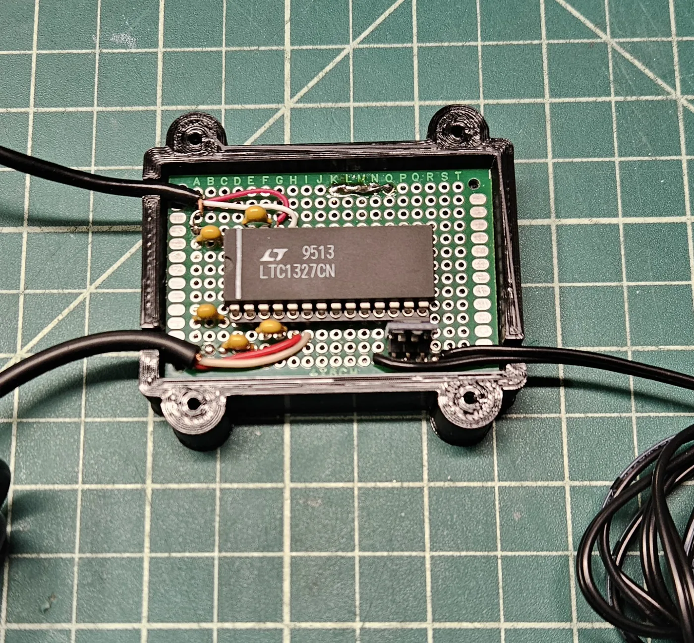
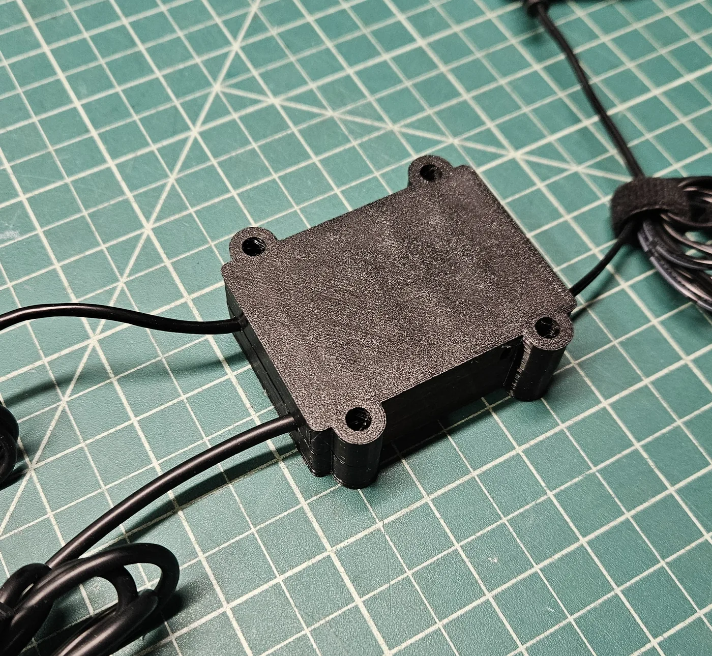
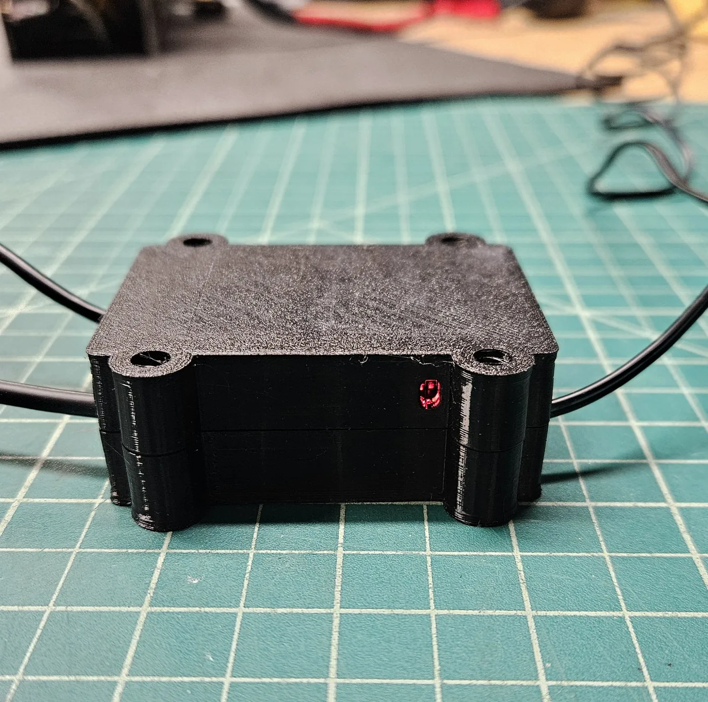
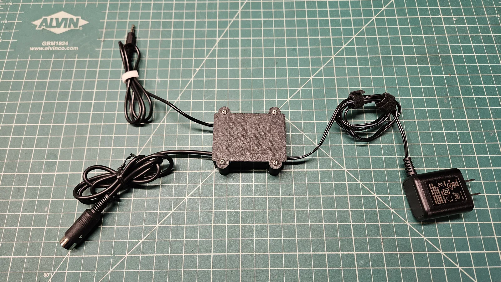
Power on: wall adapter first, then plug into the Pico. Power off: unplug from the Pico first, then the adapter.
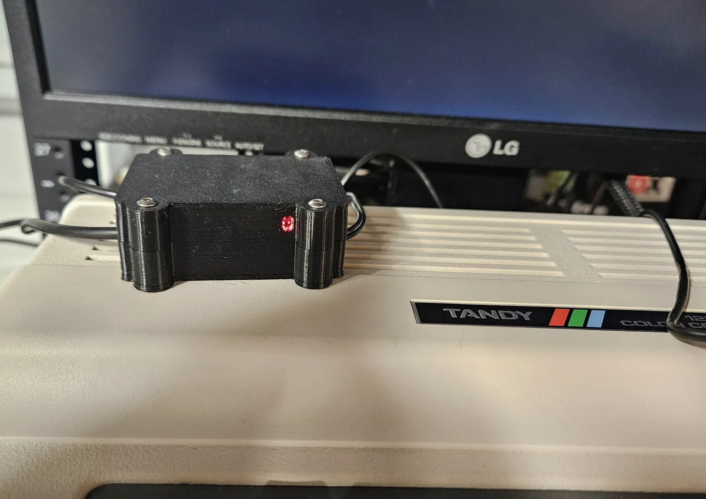
7. On the air
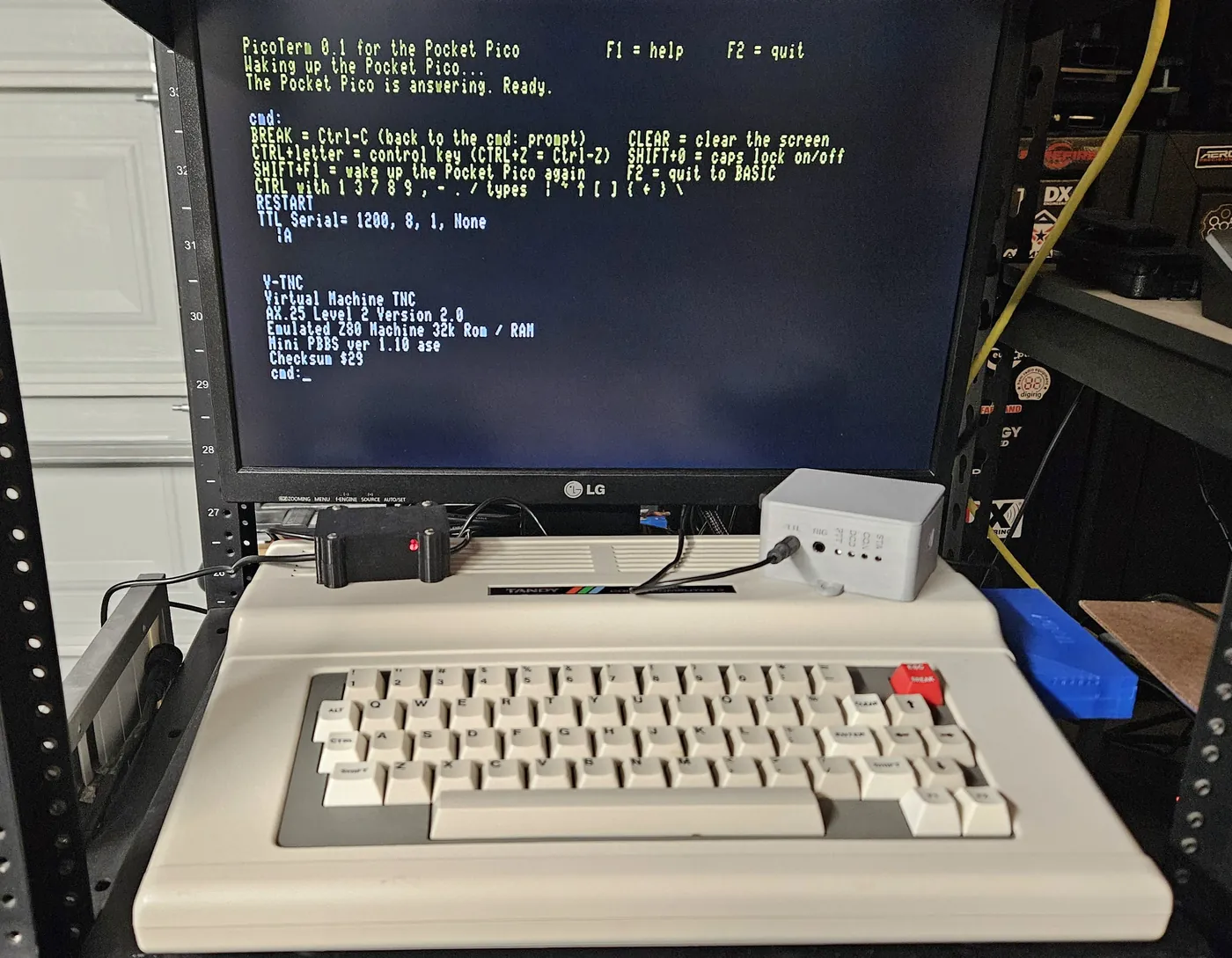
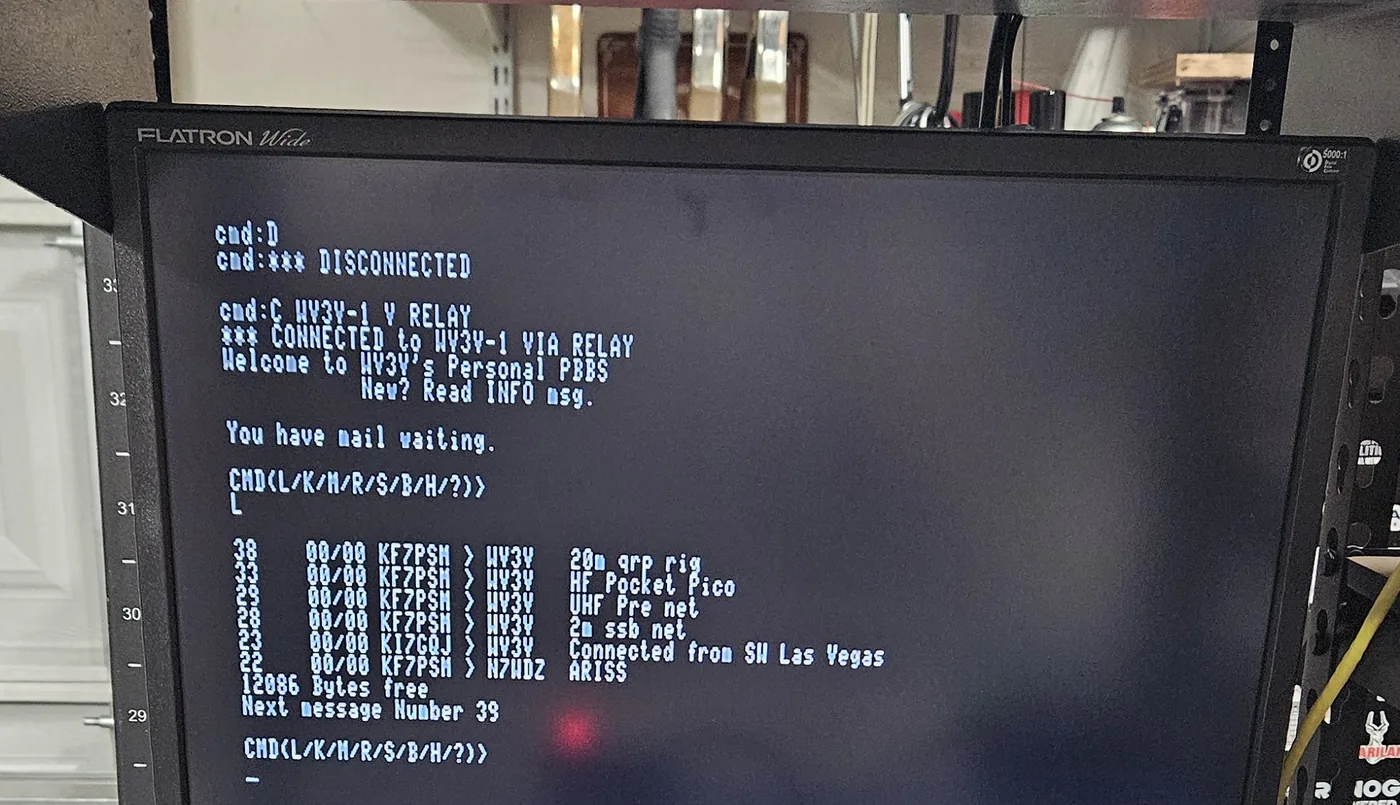
With the finished cable, PicoTerm found the Pico right away. I connected to KF7PSM-1, then to WV3V-1 through a relay, and read the message list on its personal BBS, all with clean text.
This short video was taken during the first test of the finished cable:
8. One catch: the Pico's speed
The HK-21 ROM inside the Pocket Pico sets its serial speed from a *, but only on a brand-new,
never-set-up Pico. The Pico saves its settings to flash memory, so one that has been used at another speed
(115200 is common) keeps that speed and won't answer PicoTerm. That is what happened on my first test.
The fix is done once, over the Pico's USB port with any terminal program such as PuTTY. ABAUD 1200
sets the speed, but the Pico only saves to flash when TXDELAY changes (or a new BBS message arrives), so
changing TXDELAY up one and back forces the save:
TXDELAY          (note the number, n)
ABAUD 1200
TXDELAY n+1
TXDELAY n
RESTART          (shows TTL Serial= 1200, 8, 1, None)
Don't use RESET for this: it brings back the * auto-baud but erases all of the
Pico's settings. To go back to 115200 later, do the same with ABAUD 75.
Get PicoTerm
PicoTerm is free and open source (MIT license). The GitHub page has the disk image ready to copy to an SD card, the 6809 source code, the cable notes, the Pocket Pico 1200 baud steps, a printable quick reference card and the 3D-printable case.
Credits
The Pocket Pico and its Pico TNC firmware are by Peter, KF7PSM, who also donated the ICL232 test cable and the LTC1327 chip for the finished cable. PicoTerm was written with the help of Claude, an AI assistant.