
12 V Bias-T for the MLA-30 Loop
Swapping the USB-powered bias-T that came with my MLA-30 magnetic loop for a 12 volt one, in a shielded metal case with a Powerpole input.
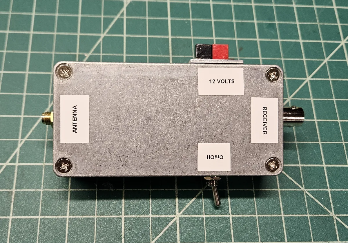
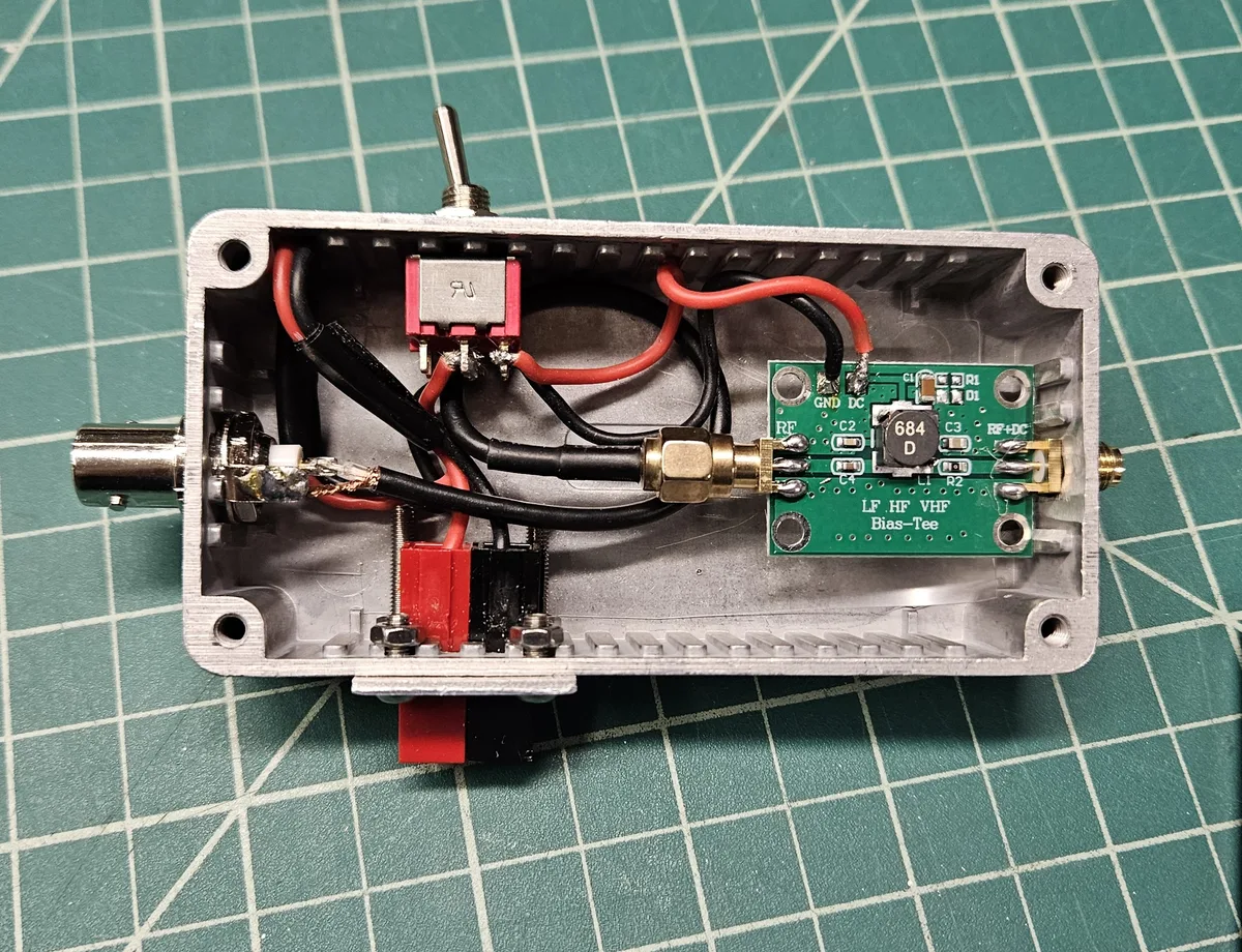
A bias-T sends DC power up the same coax that carries the signal, which is how an active antenna like the MLA-30 magnetic loop gets its power without a separate wire. The one supplied with my loop was powered from USB. I wanted the supply voltages in the ham shack to be as consistent as possible, so I replaced it with a 12 volt bias-T. The MLA-30 will run on up to 15 volts, so 12 is well within its range.
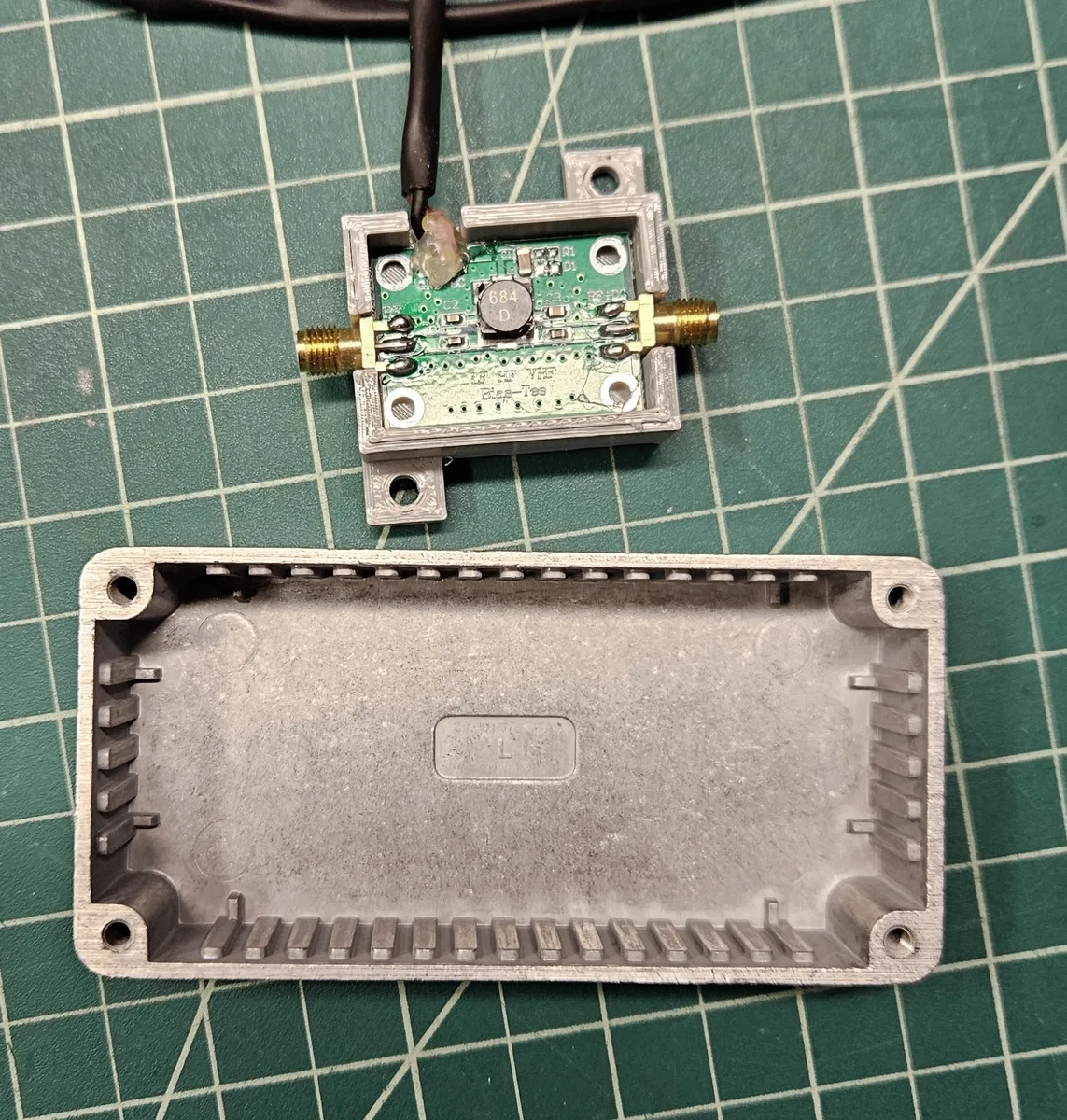
I built it into a shielded metal case. I had first 3D-printed a PETG case for the board, but I quickly decided against it and went with metal, to help keep stray RF from the transmitters around the shack out of the bias-T. In use, I noticed there is less noise on the receive signal than there was with the original.
The build
- Parts. A small bias-T board, plus a die-cast aluminum box from Jameco (3.9 × 2 × 1 inches), which I built up in the spring of 2025.
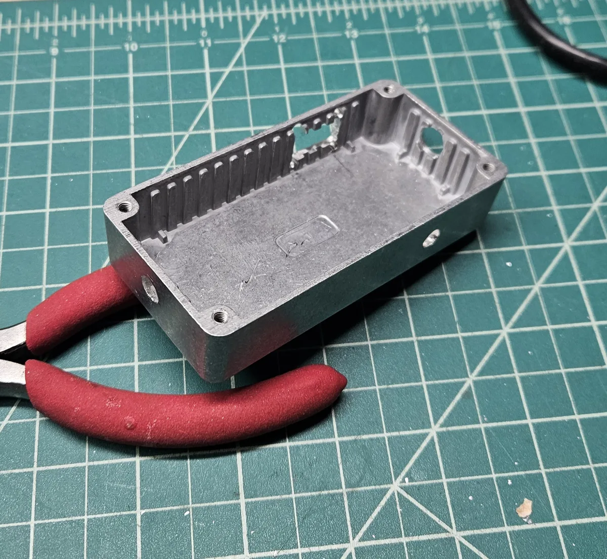
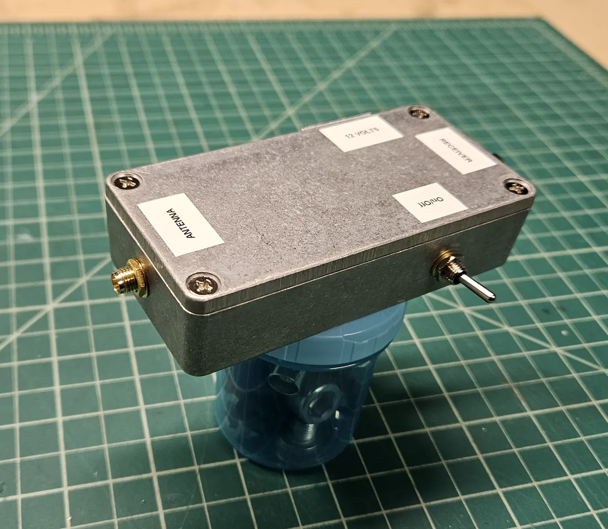
- Drilling. The box needs holes for the antenna jack, the receiver jack and the on/off toggle switch, and a square opening on the side for the power input, which I cut with a Dremel.
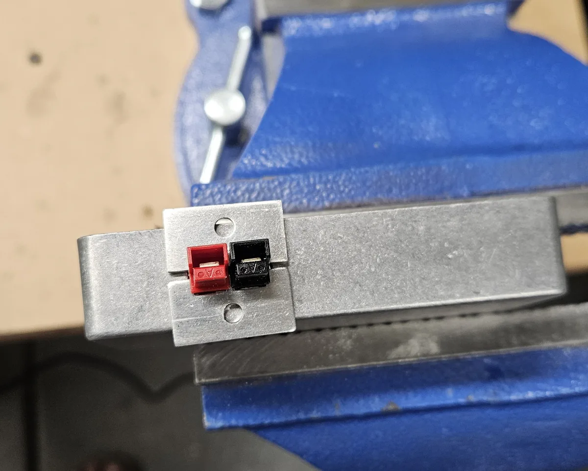
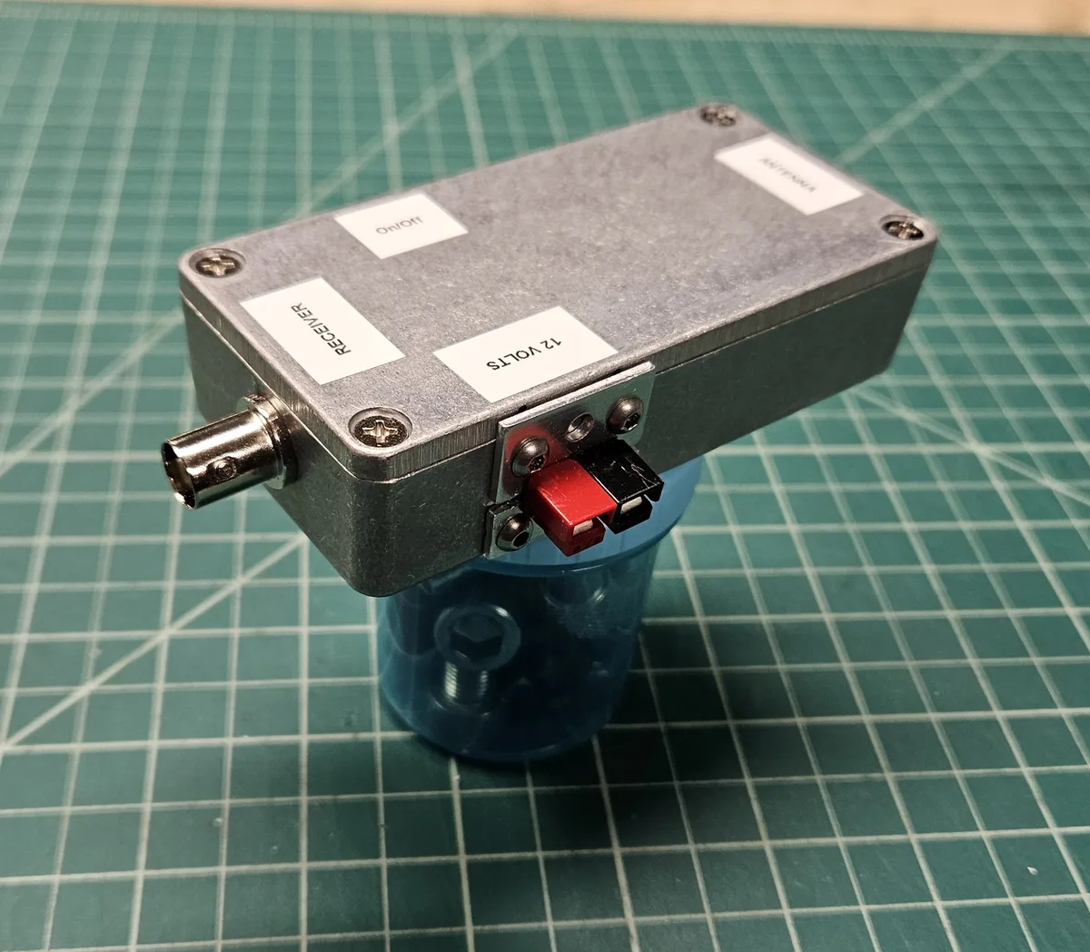
- Powerpole input. The 12 volts comes in on an Anderson Powerpole pair held in a small metal bracket on the side of the box, so it plugs into the same power as the rest of my gear.
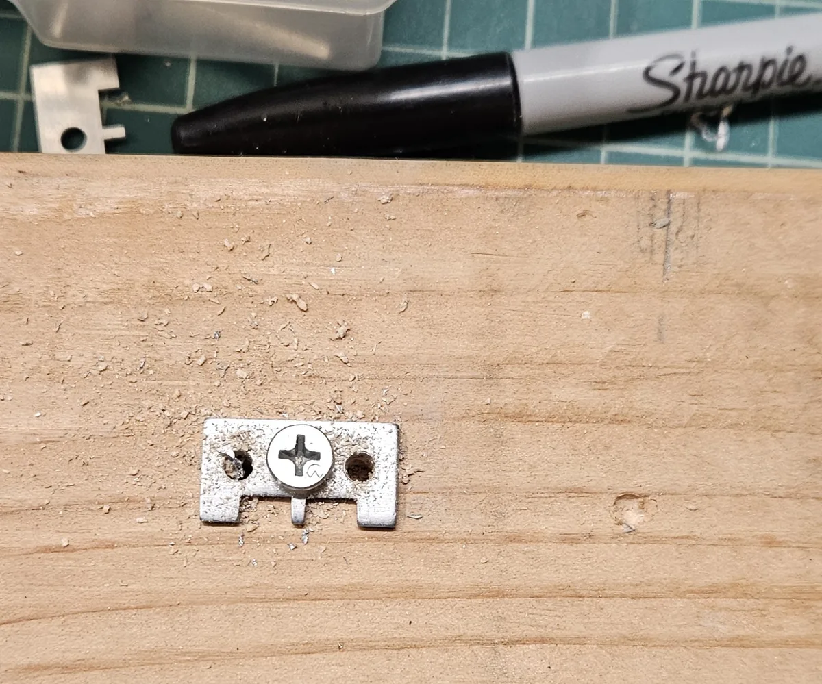
- Bracket fix. Only after the holes were in the box did I find that the Powerpole bracket hung past the bottom edge. I cut one side off so the edge of the connector lines up with the edge of the box, then drilled new mounting holes in what was left.
- Wiring. The antenna comes in on an SMA jack and goes out to the receiver on a BNC, since the receiver uses BNC too. The Powerpole feeds the board through the toggle switch.
- Labels. ANTENNA, RECEIVER, 12 VOLTS and ON/OFF, so I never have to guess which is which.
Parts
- Ciglow amplifier bias-T, 25 kHz–100 MHz, wideband coaxial feed (the original listing is gone now)
- Jameco die-cast aluminum case, 3.9 × 2 × 1 in, part number 03-125A (Jameco item 11957)
- Anderson Powerpole pair with a small mounting bracket
- SMA and BNC jacks for the antenna and receiver connections
- An on/off toggle switch